


Home > Product Information > Stepping Motors >
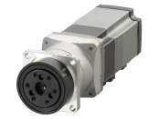
AZ Series AC Input Pulse Input Type > List of Product > AZM66MC-HP5F+AZD-A+CC040VZFB

- Accessory
- Control Circuit: Connector for the Main Power Supply and Regeneration Unit(CN4) , I/O Signals Connector(CN5) , Connector for 24 VDC Power-Supply Input/Electromagnetic Brake Connection/Regeneration Unit Thermal Input/Power Cutoff Signal I/O(CN1) , Connector wiring lever
- Safety Standards
-


| Product Type | Product Name | ProductLeadtime | UnitPrice(USD) | |
|---|---|---|---|---|
| Motor | AZM66MC-HP5F | 16 Working Days | 1,109.00 | |
| Control Circuit | AZD-A | 11 Working Days | 517.00 | |
| Connection Cables | CC040VZFB | 11 Working Days | 106.00 |
Forbetterservices,MalaysiacustomersandThailandcustomerspleasecontactourMalaysiaandThailandbranch.
●Production Information
Current product
| Frame Size | 60mm |
|---|---|
| Type | HPG Geared Type (Flange Output Type) |
| Shaft Type | Single Shaft |
| Electromagnetic Brake | With |
| Driver Type | Pulse Input Type |
| Maximum Holding Torque | 5.9N・m |
| Rotor Inertia J | 530×10^-7kg・m^2 |
| Backlash | 3arcmin (0.05°) |
| Speed Range | 0~900r/min |
| Gear Ratio | 5 |
| Resolution Setting: 1000 P/R | 0.072°/Pulse |
| Rated Torque | 5.9N・m |
| Power Supply Input Voltage | Single-Phase 100-120VAC |
| Power Supply Input Permissible Voltage Range | -15~+6% |
| Power Supply Input Frequency | 50/60Hz |
| Power Supply Input Current | 3.8A |
| Logic Power Supply | DC24V±5% 0.5A ※2 |
| CE Marking | affixed |
| Data Setting Software | MEXE02 |
| Mass: Motor | 2.2kg |
| Mass: Control Circuit | 0.65kg |
- Inertial J:86×10^-7kg・m^2 ※1
Maximum Instantaneous Torque:*
Runout of Output Flange Surface:0.02mm / Runout of Output Flange Inner Diameter:0.04mm
Holding Torque at Motor Standstill:3N・m(Power ON) / 3N・m(Electromagnetic Brake)
Connection Cable Length:4m
- * For the geared motor output torque, refer to the Speed – Torque Characteristics.
※1 The values for the moments of inertia within the gear that has been converted to motor shaft values.
※2 For the electromagnetic brake type, the 24 VDC±4% specification applies if the wiring distance between the motor and driver is extended by 20 m using a cable.
● The motor cable and electromagnetic brake cable from the motor cannot be directly connected to a driver.
To connect the motor to the driver, use a connection cable.
The link of Web2CAD site can be used for 3D CAD data downloading as well. For more details, please click here.
| 2D-CAD | Motor | B1225.dxf |
|---|---|---|
| Control Circuit | B1097.dxf | |
| 3D-CAD | Motor(STEP) | B1225.zip |
| Control Circuit(STEP) | B1097.zip | |
| 3D-CAD(web2CAD) | Motor | to web2CAD site |
| Control Circuit | to web2CAD site | |
| Document | APPENDIX UL Standards for AZ Series | HM-60247E.pdf |
| UL Certification(Motor) | UL_E336472V2S1.pdf | |
| UL Certification(Circuit) | UL_E171462V4S9.pdf | |
| Functional Safety Certificate(Circuit) | TUVSUD_Z10_106467.pdf | |
| CE/UKCA Declaration of Conformity | DoC-6083.pdf | |
| RoHS Compliance Declaration | EU_RoHS_AZ.pdf | |
| Operating Manual | AZ Series Cable Type Motor Edition | HM-60244E.pdf |
| AZ Series AC power input Driver | HM-60314E.pdf | |
| AZ Series Function Edition | HM-60262E.pdf |
| Dimension |
|---|
|
Motor Control Circuit Cable |
| Characteristics Diagram |
|---|
|
Speed - Torque Load Torque - Driver Input Current |
| Other specifications |
|---|
|
Other specifications Driver Specifications |