


Home > Product Information > Stepping Motors >
AZ Series EtherCAT Compatible > List of Product > AZM98AC-HP5+AZD-CED+CC030VZF
- Accessory
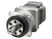
- Motor : Parallel Key
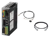
Control Circuit: Connector for the Main Power Supply and Regeneration Unit (CN4)、Connector for 24 VDC Power-Supply Input/Electromagnetic Brake Connection/Regeneration Unit Thermal Input/Power Cutoff Signal I/O(CN1)、I/O Signals Connector(CN7)、Connector wiring lever
Cable:Connection cable is 3m long. Flexible Cable types and other lengths are available. For details, please refer to the cable dimensions.
- Safety Standards
-


| Product Type | Product Name | ProductLeadtime | UnitPrice(USD) | |
|---|---|---|---|---|
| Motor | AZM98AC-HP5 | 16 Working Days | 1,159.00 | |
| Control Circuit | AZD-CED | Please contact us for more info | Please contact us for more info | |
| Connection Cables | CC030VZF | 11 Working Days | 57.00 |
You cannot add this product to a cart. Sorry for your inconvenience but please contact to customer support centre.
●Production Information
Current product *Cables are available in flexible types and other lengths.
| Frame Size | 90mm |
|---|---|
| Type | HPG Geared Type |
| Shaft Type | Single Shaft |
| Electromagnetic Brake | Not Equipped |
| Cable | 3m(Standard Cable) |
| Driver Type | EtherCAT Drive Profile Compatible |
| Maximum Holding Torque | 10N・m |
| Rotor Inertia J | 1090×10^-7kg・m^2 |
| Backlash | 3arcmin (0.05°) |
| Speed Range | 0~900r/min |
| Gear Ratio | 5 |
| Resolution Setting: 1000 P/R | 0.072°/Pulse |
| Rated Torque | * |
| Power Supply Input Voltage | Single-Phase/Three-Phase 200-240VAC |
| Power Supply Input Permissible Voltage Range | -15~+6% |
| Power Supply Input Frequency | 50/60Hz |
| Power Supply Input Current | Single-Phase 200-240VAC:3.3A Three-Phase 200-240VAC:2.0A |
| Logic Power Supply | DC24V±5% 0.25A |
| CE Marking | affixed |
| Data Setting Software | MEXE02 |
| Mass: Motor | 4.8kg |
| Mass: Control Circuit | 0.68kg |
- ●Moment of Inertia J:629×10^-7kg・m^2 ※
●Maximum Instantaneous Torque:*
●Holding Torque at Motor Standstill:5N・m(Power ON)
- * For the geared motor output torque, refer to the Speed – Torque Characteristics.
※ his is the internal inertia of the gear converted to the motor shaft.
The link of Web2CAD site can be used for 3D CAD data downloading as well. For more details, please click here.
| 2D-CAD | Motor | B1187.dxf |
|---|---|---|
| Control Circuit | B1504.dxf | |
| 3D-CAD | Motor(STEP) | B1187.zip |
| Control Circuit(STEP) | B1504.zip | |
| 3D-CAD(web2CAD) | Motor | to web2CAD site |
| Control Circuit | to web2CAD site | |
| Document | APPENDIX UL Standards for AZ Series | HM-60247E.pdf |
| UL Certification(Motor) | UL_E336472V2S1.pdf | |
| UL Certification(Circuit) | UL_E171462V4S9.pdf | |
| CE/UKCA Declaration of Conformity | DoC-6083.pdf | |
| Functional Safety Certificate(Circuit) | TUVSUD_Z10_106467.pdf | |
| RoHS Compliance Declaration | EU_RoHS_AZ.pdf | |
| ESI File | ORIENTALMOTOR_AZD-CED_rev0000.xml | |
| Catalogue | AZ Series EtherCAT Compatible Driver | AZ EtherCat flyer_EN.pdf |
| Operating Manual | AZ Series Cable Type Motor Edition | HM-60244E.pdf |
| AZ Series/Motorized Actuator equipped with AZ Series EtherCAT Drive Profile Compatible USER MANUAL | HM-60375E.pdf | |
| AZ Series Function Edition | HM-60262E.pdf |
| Dimension |
|---|
|
Motor Control Circuit Cables(0.5m-20m) |
| Characteristics Diagram |
|---|
|
Speed - Torque Load Torque - Driver Input Current |
| Other specifications |
|---|
|
Other specifications |