Cables: For MSC-1

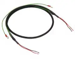
Connection Cable
Cable suitable for connection between speed control motors and speed controllers. Product line differs depending on the motor output power.
Cable Specifications
| Product Name | Core Number Configuration | AWG | Insulator Outer Diameter | Finished Outer Diameter | Rating | Outer Diameter Sheath | ||
|---|---|---|---|---|---|---|---|---|
| CC05SS3 CC10SS3 |
8 cores | For Motor | 4 | 20 | φ2.7 | φ11 | 80 °C 300 V |
Heat-resistant vinyl chloride |
| For signals | 2 | 24 | φ1.7 | |||||
| For Cooling Fan | 2 | 24 | φ1.7 | 105 °C | ||||
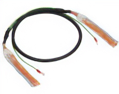
Connection Cable: DC Power Supply Cable
Shielded cable for connection of DC power supply and electromagnetic brake. Ground wire with round terminal for easy shield grounding.
| Product Name | Length (m) |
AWG | Insulator Outer Diameter | Finished Outer Diameter | |
|---|---|---|---|---|---|
|
CC02D005-3 | 0.5 | 20 | φ1.65 | φ5.9 |
| CC02D010-3 | 1 | ||||
| CC02D015-3 | 1.5 | ||||
| CC02D020-3 | 2 | ||||
| CC02D050-3 | 5 |
General-Purpose Cable: For I/O Signals
Shielded cable for I/O signal wiring of various speed controllers and drivers. Ground wire with round terminal for easy shield grounding. Marked tubes are provided for easy identification of lead wires.

| Product Name | Length (m) |
Number of Cores | AWG | Insulator Outer Diameter | Finished Outer Diameter | |
|---|---|---|---|---|---|---|
|
CC06D005B-1 | 0.5 | 6 | 24 | φ1.1 | φ5.4 |
| CC06D010B-1 | 1 | |||||
| CC06D015B-1 | 1.5 | |||||
| CC06D020B-1 | 2 | |||||
| CC10D005B-1 | 0.5 | 10 | φ6.7 | |||
| CC10D010B-1 | 1 | |||||
| CC10D015B-1 | 1.5 | |||||
| CC10D020B-1 | 2 | |||||
| CC12D005B-1 | 0.5 | 12 | φ7.5 | |||
| CC12D010B-1 | 1 | |||||
| CC12D015B-1 | 1.5 | |||||
| CC12D020B-1 | 2 |
- * Please select the number of cores required according to the function to be used.
Cable Note When Wiring Flexible Cable
Do not bend the cable at the connector. Stress applied to the connectors and terminals causes poor contact and disconnection.
How to Fix the Cable
Fix the connector part in 2 places to prevent it from moving.
Wiring Length and Bending Radius of the Cable
Wiring should be installed at an appropriate length, so that cables are not pulled during movement.
In addition, the bending radius (R) should be 6 times the cable diameter min.
Interference of the Cable
Wire the cables in the cable holder without bringing them into contact with each other. This will add stress to the cable, and cause it to break prematurely. Please check note on cable holders carefully before use.
Cable Kinks
◇Please wire without kinks in the cable. Kinking in a twisted state can cause premature disconnection. After wiring, confirm that there are no kinks in the cable, using the print on the cable surface as a reference.