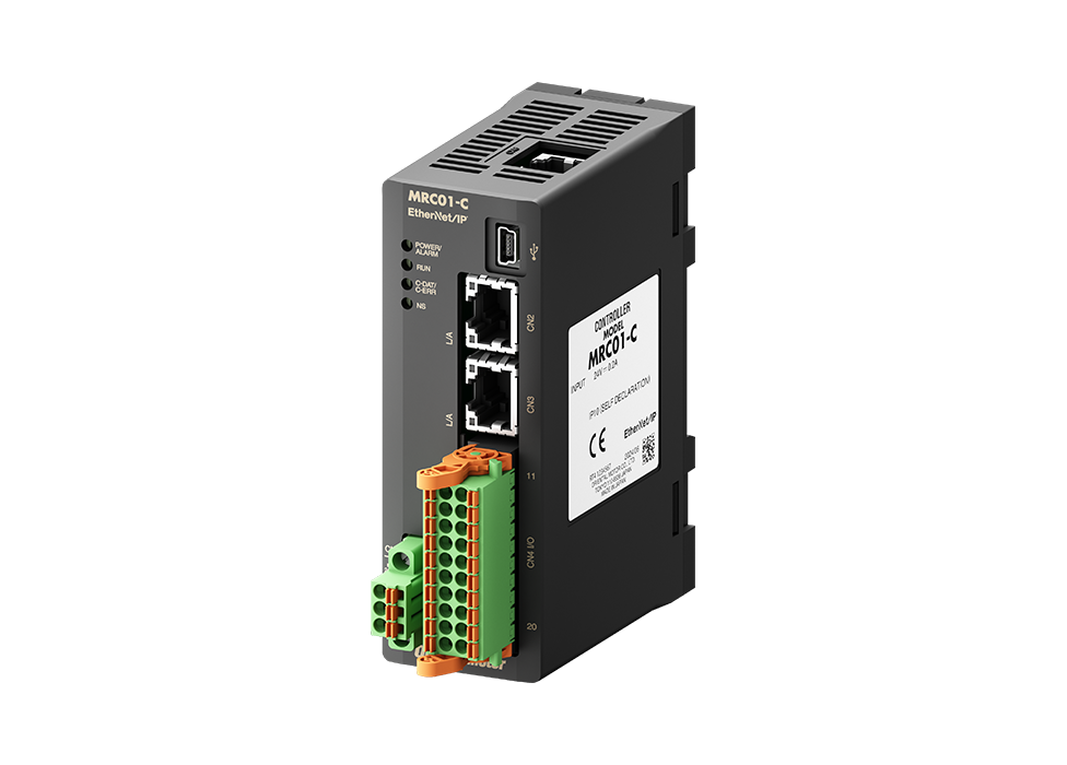
Robot Controller
MRC01-C
- Easy Introduction and Control of Robots
- Easy Setup With Programming Software
- Dedicated, Low-Cost Controller for Cartesian Robots
Tính năng |Robot Controller MRC01-C
- Dedicated Controller for Cartesian Robots
- Easy Operation for Machine Designers With No Experience in Sequence Control Using PLCs
- Easy Introduction of Robots Into Existing Systems
- Easy setup with the robot controller MRC01-C and the programming software MRC Studio
- Linkage Function With 2D Vision Sensor to Automate More Advanced Operations
- Multiple User Coordinate Systems (Load coordinate systems) Can be Set
- MRC Studio Simulator (Free of charge) Allows You to Check the Robot's Operation During the Pre-purchase Review Phase
- Products for Combination
Dedicated Controller for Cartesian Robots

The MRC01-C is a dedicated controller for cartesian robots. This controller is used in the following cases:
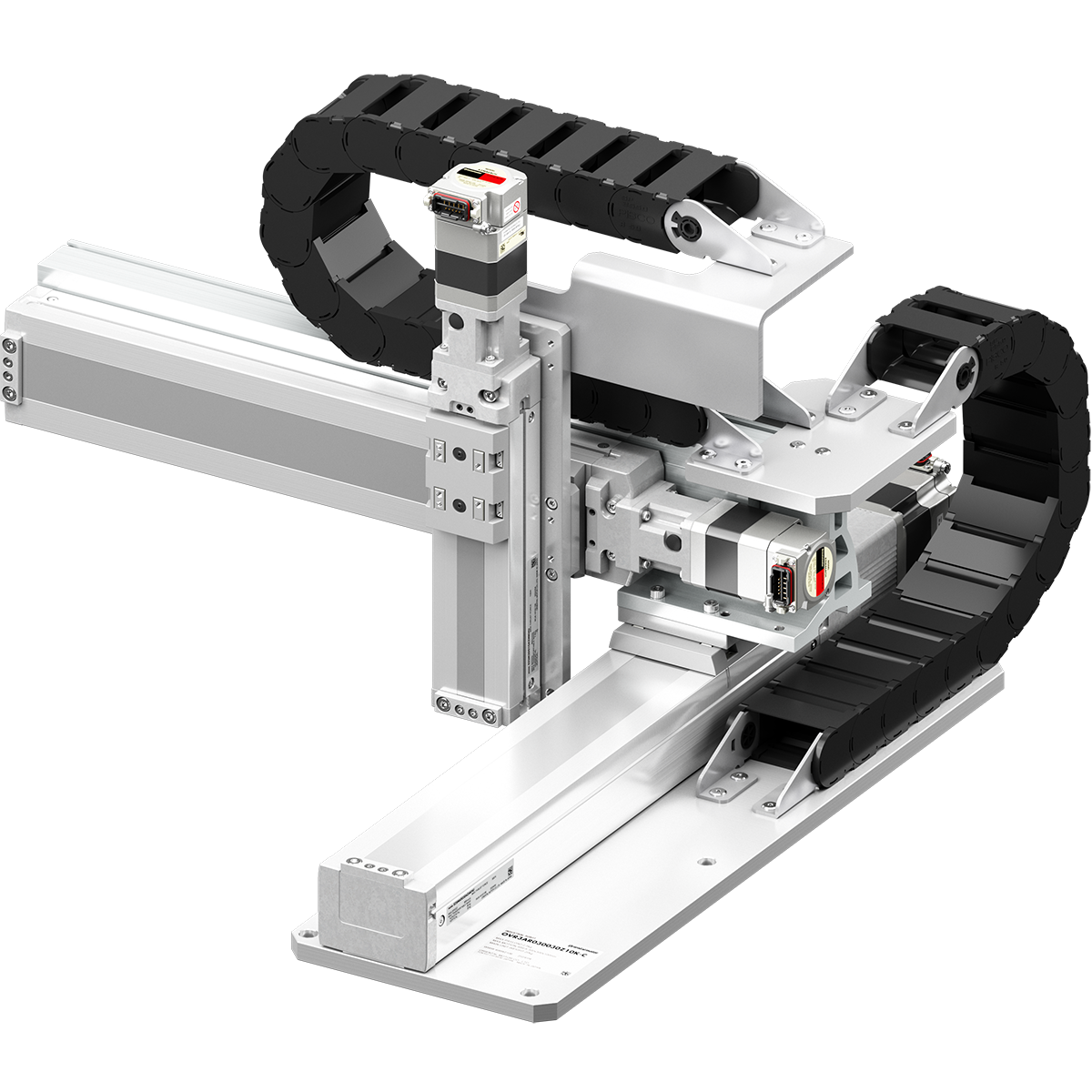
- To control Small Robots OVR 3-axis cartesian
Click here for details on the OVR 3-axis cartesian - To control in-house cartesian robots using the AZ Series
Click here for details on the EZS Series
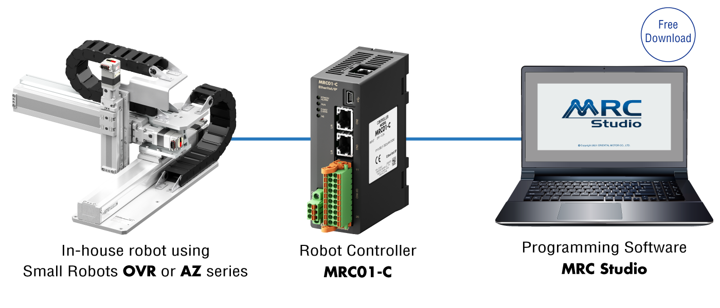
Easy Operation for Machine Designers With No Experience in Sequence Control Using PLCs
The MRC01-C can easily teach and check operation programs set up with the MRC Studio programming software using only a PC.
Easy Introduction of Robots Into Existing Systems
MRC01-C links to the host controller using Ethernet/IP™ for direct control. The Small Robots OVR or in-house robots can be easily added to existing equipment without making significant changes to the control system.
- *EtherNet/IP™ is a trademark of ODVA.
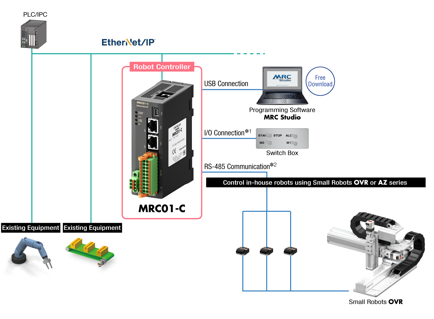
- *1
- The MRC01-C can also be operated with an I/O connection (without a host controller).
- *2
- The MRC01-C and AZ Series driver are controlled by RS-485 communication.
Easy Setup With the Robot Controller MRC01-C and the Programming Software MRC Studio
The "MRC Studio programming software" is available for easy setup of in-house robots from initial settings to operation programming.
The "MRC Studio Simulator" that enables teaching without communication with the MRC01-C is also available. Programs created with MRC Studio Simulator can be used without change when installing actual robots.
Both software packages are available for free download.
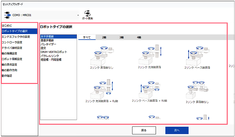
Step 1. Follow the Guide to Complete Initial Settings Without Getting Lost.
The wizard provides guidance for carrying out a variety of initial settings such as robot type selection and mechanism information input. By following the directions and illustrated instructions, even first-time users can complete the initial settings for robots in a short time. The Small Robots OVR has pre-input mechanism information, making it easier to perform the initial settings.
Follow the Steps to Set Up
Follow the wizard menu to proceed with the initial settings of the robot.
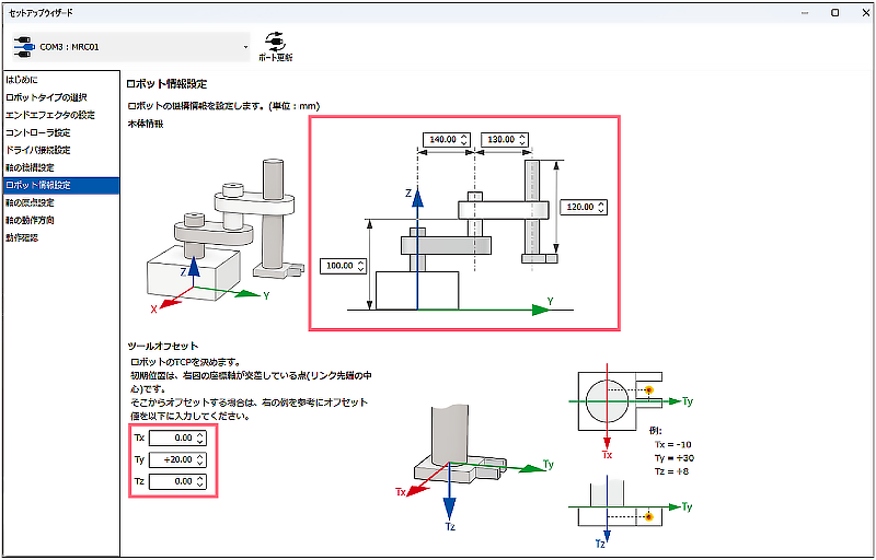
Input Arm Length and Other Dimensions While Looking at the Illustration of the Robot
Dimensions are entered directly in the input boxes in the illustration.
Select Robot Type
(Typical example)
| Cartesian | Small Robots OVR Cartesian |
|
|---|---|---|

|

|
|
| XYZ | Planar surface gantry (XY) | OVR3AR030030Z10K-C (3-axis) |
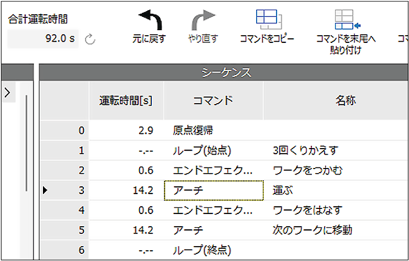
Step 2. Knowledge of Ladders not Required. Program Operations by Selecting Items.
Simply select commands to create a program. Programs can be created intuitively without specialized knowledge such as ladders. Compatible with a variety of operations, such as PTP operation, linear interpolation operation, circular interpolation operation, and arch motion. In addition, direct operation data operation can also be performed via EtherNet/IP from the host controller.
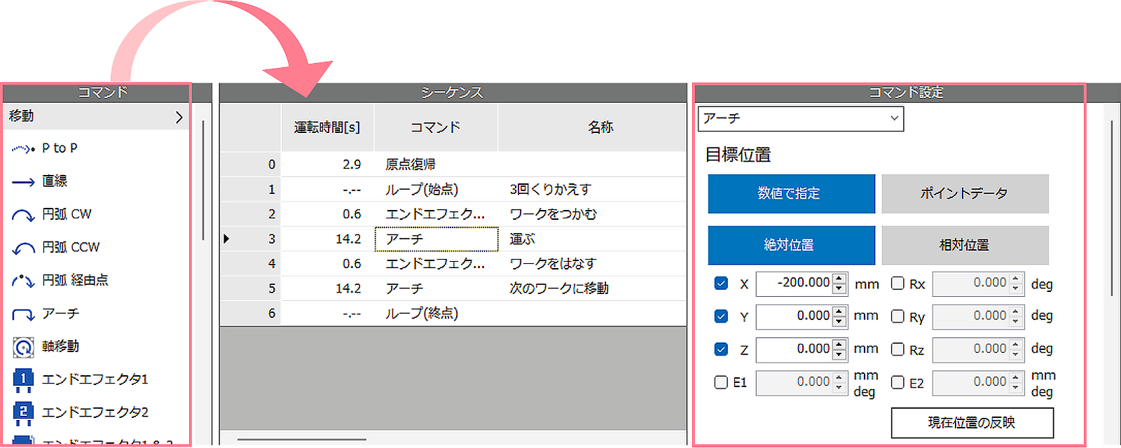
Drag and Drop the Necessary Commands
Select the desired action from the "Command" column and drag and drop it into the "Sequence" column to display the "Command Settings" column.
Set Target Position and Speed
Specify the coordinates and travel distance of the target position and enter the speed in the command setting field.
| Command | ||||
|---|---|---|---|---|

|

|

|

|

|
| PTP Control | Linear Interpolation | Circular Interpolation (Helical interpolation) | Arch Motion | Palletizing |
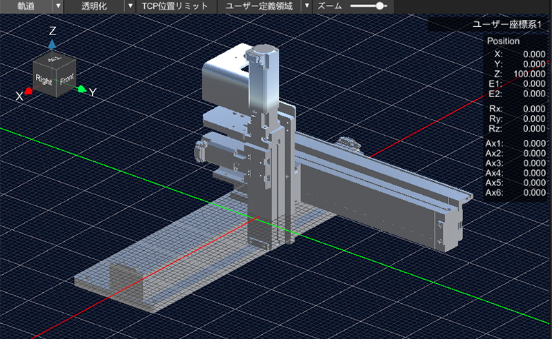
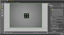
Step 3. Operation Confirmation Using an Online 3D Simulator
The program operation time can be displayed and the program contents can be verified considering the robot's movable range, etc.
It is possible to check the operation on 3D graphics without moving the actual device.
- *There may be differences between simulation and actual operation.
- *Simulation requires communication with MRC01-C.
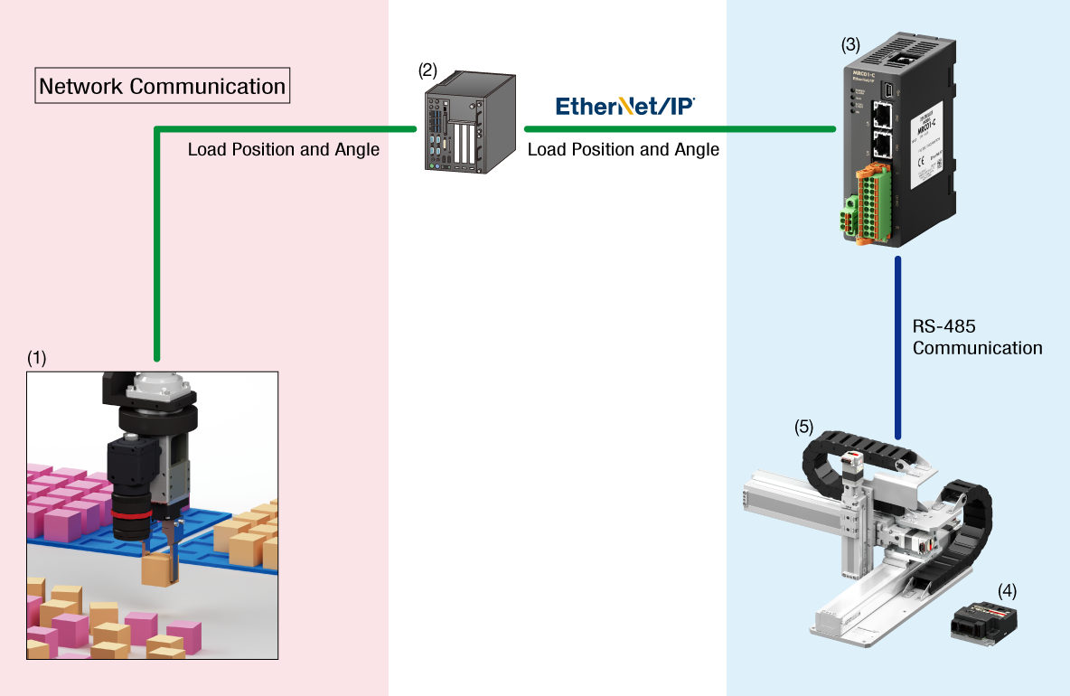
Linkage Function With 2D Vision Sensor to Automate More Advanced Operations
Building a Robot Vision System Using a 2D Vision Sensor
The robot controller MRC01-C is equipped with useful functions for driving the robot using information on the position and angle of the load acquired by the Vision Sensor.
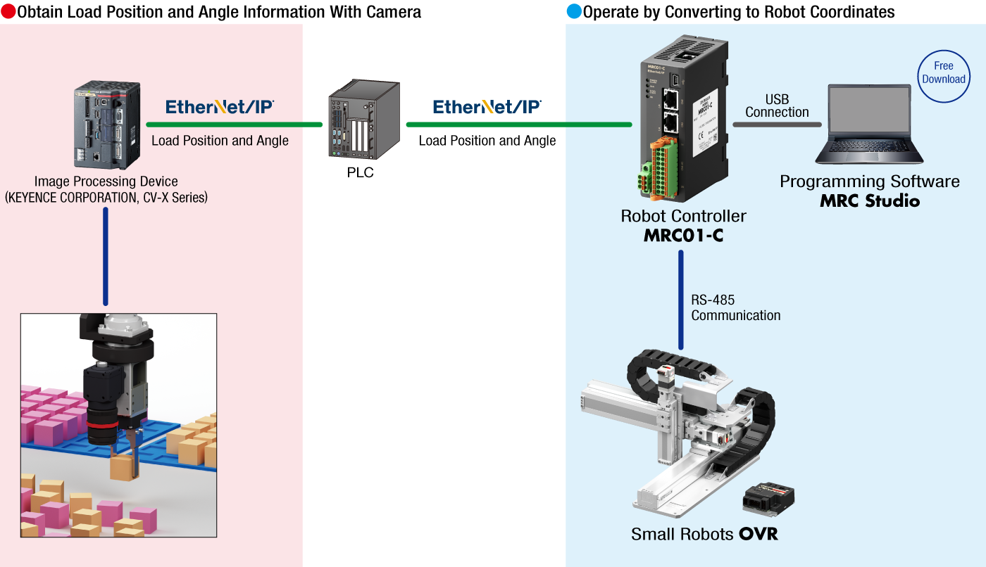
About Compatible Models of Image Processing Device and PLCs
The above configuration diagram is an example of connection with the CV-X Series manufactured by KEYENCE CORPORATION.
Refer to here for support status of processing software from other companies
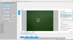
About Calibration
In order to work with a 2D camera, the camera is pre-calibrated using MRC Studio. The settings can be easily configured by simply following the on-screen instructions while looking at the illustrations, reducing the man-hours required for correction. (Up to 2 cameras can be calibrated.)
Compatibility With Vision Sensors and Image Processing Software From Other Companies
Vision sensors and image processing software that have been confirmed to work in combination with MRC01.
| Manufacturer | Vision Sensor、Processing Software | System Configuration Example |
|---|---|---|
| KEYENCE | XG-X | ① |
| CV-X | ||
| VS-L | ② | |
| Mitsubishi Electric | VS80 | |
| COGNEX | In-Sight 2800M | |
| In-Sight 8000 | ||
| MVTec Software | MERLIC | ③ |
| HALCON | ||
| CKD | Facilea |
System Configuration Example①
This is an example of a general configuration of a robot vision system.
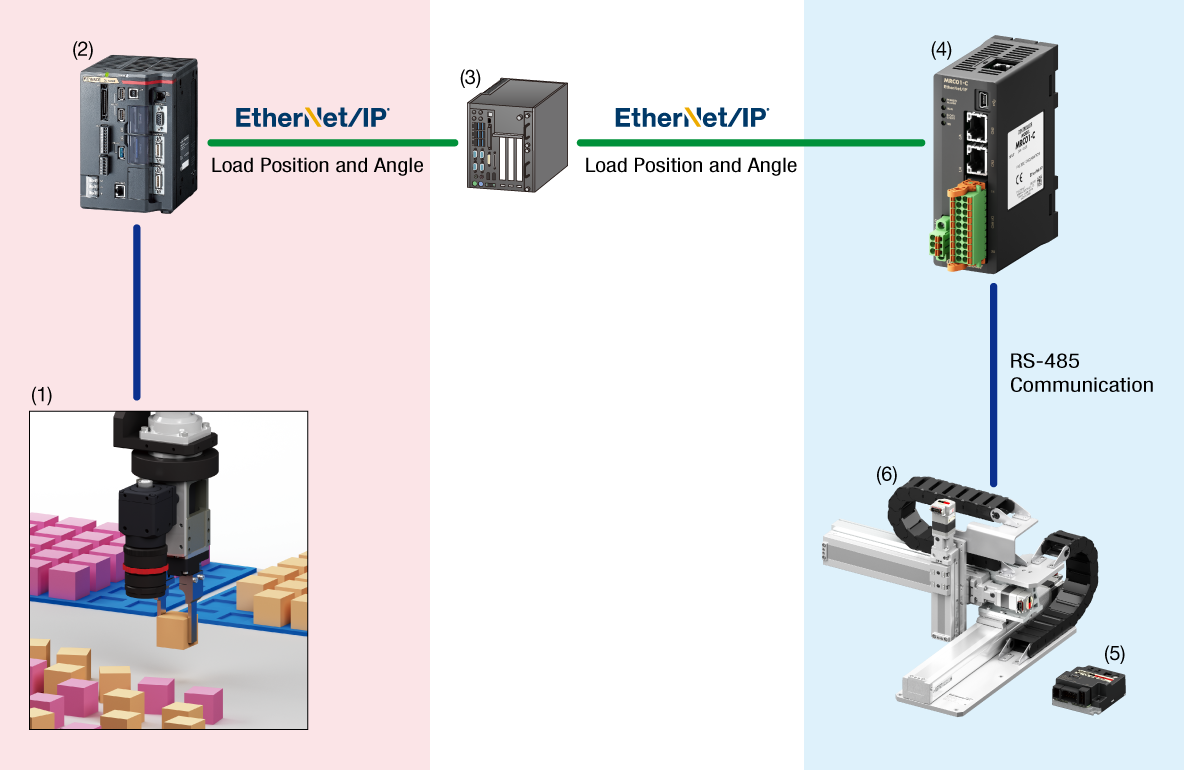
Equipment to Prepare
- Camera
- Camera Controller
- PLC
- MRC01-C
- Driver
- Robot
System Configuration Example②
This is an example of a configuration in which a camera controller is built into the camera.
Simple system configuration is possible.
Equipment to Prepare
- Camera
- PLC
- MRC01-C
- Driver
- Robot
System Configuration Example③
This is a configuration example where the camera controller functions are realized by a PC (software).
MRC01 is controlled by a PC or PLC.
Robot vision system can be built without a PLC when controlling with a PC.
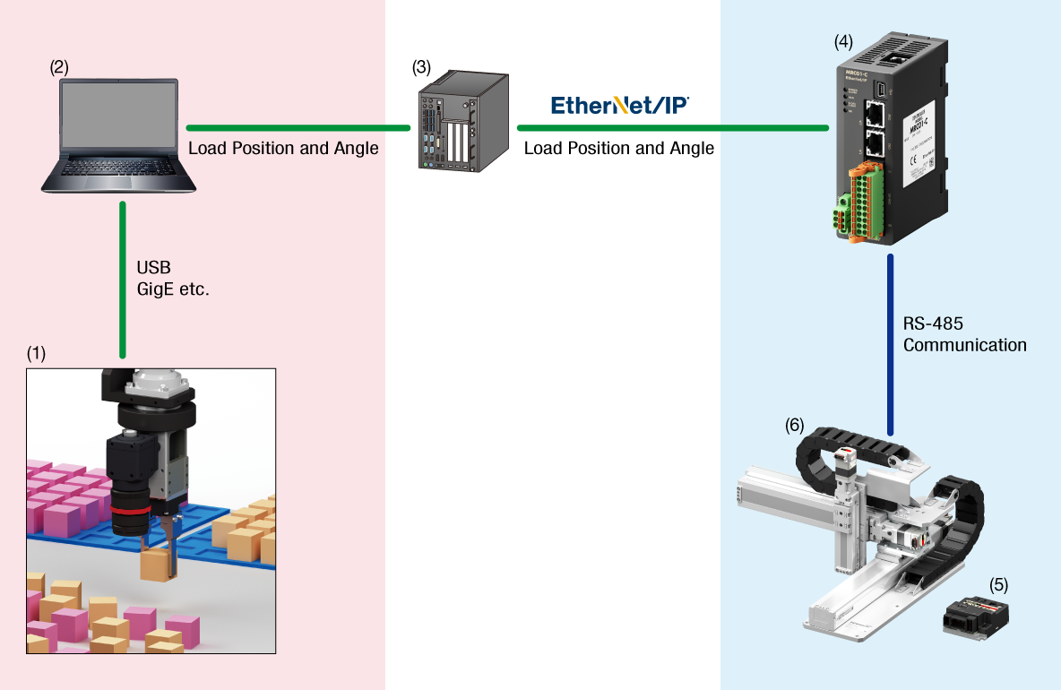
Equipment to Prepare
- Camera
- PC
- PLC*
- MRC01-C
- Driver
- Robot
- *Please prepare, if necessary.
Application Example
There are many automations that can be realized by linking with a 2D camera, such as load position information detection, dimensional and visual inspection, etc. Here is an example.
Position Correction
Alignment of cumbersomely arranged loads (fixed camera method)
Color Recognition
Sorting loads of different colors (hand-eye method)
Multiple User Coordinate Systems (Load coordinate systems) Can be Set
This is useful when the same work is repeated in multiple work areas. It is possible to change the starting point of work without changing the operation program.
Coordinate System is Set From Teaching Screen
Up to 3 arbitrary positions can be set as the origin. Settings are made from the MRC Studio teaching screen.
-

Move the robot to the position to be set as the origin -

Select coordinate system -

Set the current position as the origin
Easy Switching Within a Single Program
The coordinate system can also be changed by the coordinate system switching command in the operation program. Multiple coordinate system switching commands can be added to a single program.
MRC Studio Simulator Allows You to Check the Robot's Operation During the Pre-purchase Review Phase
MRC Studio Simulator is software that enables simulation of actual movements without the robot itself or MRC01-C.
Operation programs created with MRC Studio Simulator can be used without change when installing actual robots.
Differences Between MRC Studio Simulator and MRC Studio (Product version)
Both are available for free download. The differences in functionality are as follows.
| Item | MRC Studio Simulator | MRC Studio (Product version) |
|---|---|---|
| Communication With the Robot Controller MRC01-C | - | ○ |
| Setup | △ | ○ |
| Items that communicate with the robot controller MRC01-C or the driver cannot be set. | ||
| Save Configuration Data File to PC | ○ | ○ |
| Open File | ○ | ○ |
| The .mrcxt file can be opened. A sample file of the configuration program is also available. |
The .mrcx file can be opened. | |
| Import data files created with MRC Studio Simulator | - | ○* |
| Teaching | ○ | ○ |
| Operation Program Creation | ○ | ○ |
| Test Operation | ○ | ○ |
| Parameter Setting | △ | ○ |
| Some parameters cannot be set. For more information, please refer to [Help] → [Open how to use] in MRC Studio Simulator. |
||
| Monitoring | △ | ○ |
The following can be monitored.
Information on signal systems that require connection to external devices cannot be monitored. |
- *The MRC Studio Simulator does not take into account the load condition of each axis, which may cause differences in actual operation.
When operating the actual device for the first time, we recommend that you try a lower operating speed rate.
Products for Combination
In addition to the Small Robots OVR (3-axis cartesian), it can be combined with the AZ Series or electric actuators equipped with the AZ Series.
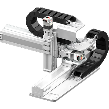
Small Robots OVR (3-axis cartesian)
AZ Series

Electric Actuators


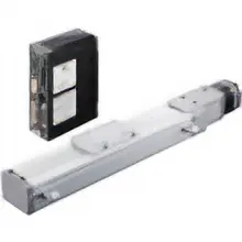
Electric Linear Slides EZS Series
For Clean Room Use


Thu hẹp phạm vi sản phẩm