Servo Motors NX Series
NX975MS-1
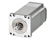
Motor/Control Circuit
| Phân loại sản phẩm | Tên sản phẩm | Giá niêm yết | Giá niêm yết | Ngày vận chuyển |
|---|---|---|---|---|
| Motor / Control Circuit | NX975MS-1 | SGD 2,348 | USD 1,878 | Sản phẩm dự kiến ngừng sản xuất (30.1.2026 Đơn hàng cuối cùng) |
- *Vui lòng liên hệ với chúng tôi về việc mua sản phẩm.
- *Sản phẩm sẽ ngừng sản xuất vào ngày 31.3.2026. Vui lòng đặt hàng trước thời hạn này.
Bao gồm
- Motor, Control Circuit, Motor Connection Cable (1 m), Encoder Connection Cable (1 m), Cable for Electromagnetic Brake (1 m), I/O Signal Connector, Motor Connector, Connector for Regeneration Resistor Input/Main Power Input Terminals, Connector for 24 VDC Power Supply Input/Regeneration Resistor Thermal Input/Electromagnetic Brake Connection Terminal, Connector Wiring Lever
Thông số kỹ thuật
Kích thước
Tải dữ liệu
Các thông số kỹ thuật khác
Driver Circuit Specifications
| Host Interface | Pulse input/analog speed command voltage/analog torque command voltage |
|---|---|
| Maximum Input Pulse Frequency | Line Driver output by Host Controller: 500 kHz (at 50 % duty) Open-Collector Output by Host Controller: 250 kHz (at 50 % duty)* |
| Protective Function |
When the following protective functions are activated, an alarm signal is output to stop the motor. Excessive position deviation, overcurrent protection, overheat protection, overvoltage protection, main power supply error, undervoltage, motor overheat protection, sensor error during operation, encoder communication error, overload, overspeed, position range error, absolute position loss, command pulse error, EEPROM error, sensor error during initialization, rotor rotation during initialization, encoder EEPROM error, motor combination error, ABS not supported, no battery, regeneration resistor overheat, electronic gear setting error |
| Input Signals |
|
| Output Signals |
|
| Other Functions | Position control, speed control, torque control, tension control Automatic tuning, damping control function (7~30 Hz), position preset function, present position output function, torque limiting function Pulse input mode (2-pulse input, 1-pulse input), analog monitor output function (speed, torque), absolute system enable/disable Warning output function (excessive position deviation, overheat, overvoltage, main power supply, undervoltage, battery undervoltage, overload, excessive speed, absolute position loss, electronic gear setting error) |
| Extended Functions [When using control module (OPX-2A) sold separately, or support software (MEXE02) ] |
For details on extended functions, refer to each control mode specification. |
- * The value when the general-purpose cable (CC36D1E) (sold separately) is used.
Position Control Mode Specifications
| Item | Factory Setting | Extended Functions |
|---|---|---|
| Command Modes |
Select 1 mode from the following pulse input modes.
|
Select 1 mode from the following pulse input modes.
|
| Maximum Input Pulse Frequency | Line Driver Output by Host Controller: 500 kHz (at 50 % duty) Open-Collector Output by Host Controller: 250 kHz (at 50 % duty)*1 |
|
| Resolution | 1000 P/R | 100~100000 P/R |
| Encoder Output Resolution | 1000 P/R | 100~10000 P/R |
| Damping Control Frequency | Disable/7~30 Hz (internal potentiometer VR1) |
Can be set with either 1 analog + 3 internal parameters for a total of 4 types, or 4 internal parameters with ① and ② below. ①
Internal potentiometer VR1 (volume) 1 type
②
3 or 4 internal parameter settings
Disable/7~30 Hz (internal potentiometer VR1) Disabled/7~100 Hz (internal parameter settings) |
| Absolute System Position Management Range |
-2,147,483,648~2,147,483,647 pulses | |
| Present Position Output | 2-bit serial output | |
| Tuning | Auto only [Auto] Select rigidity setting (SW2) from 16 levels. Estimates the load inertia, and automatically adjusts gain according to the rigidity setting. |
Auto, semi-auto, and manual selections are available. [Auto] Select rigidity setting (SW2 or internal parameter) from 16 levels. Estimates the load inertia, and automatically adjusts gain according to the rigidity setting. [Semi-Auto] Select rigidity setting (SW2 or internal parameter) from 16 levels. Enter the load inertia ratio. [Manual] Select rigidity (SW2 or internal parameter) from 16 levels. Enter the load inertia ratio. All gains can be set manually. |
| Torque Limiting | 0~300 % (100 % is the rated torque.) External potentiometer*2 (T-REF) |
0~300 % (100 % is the rated torque. Internal parameters can be set in 1 % increments) Setting by external potentiometer*2 (T-REF) and internal parameters |
- When using the extended functions, the separately sold control module (OPX-2A) or support software (MEXE02) is required.
- *1
- The value when the general-purpose cable (CC36D1E) (sold separately) is used.
- *2
- Separately-sold accessory sets are available.
Speed Control Mode Specifications
| Item | Factory Setting | Extended Functions | |
|---|---|---|---|
| Command Modes |
2 speeds can be set in ① and ② below. ①
Internal potentiometer VR1 (Volume) 1 speed
②
External potentiometer* V-REF (Volume or external DC voltage selection) 1 speed
|
Set 8 speeds with either ①, ②, or ③ below, for a total of 2 analog speeds + 6 internal parameter settings, or 8 internal parameter settings. ①
Internal potentiometer VR1 (Volume) 1 speed
②
External potentiometer* V-REF (Volume or external DC voltage selection) 1 speed
③
Internal parameter setting 6 speed or 8 speed
|
|
| Speed Setting Range | 10~5500 r/min (Analog speed setting VR1, V-REF) | 10~5500 r/min (Analog speed setting VR1, V-REF) 1~5500 r/min (Internal parameter settings) |
|
| Acceleration/Deceleration Time Setting Range | 5 ms~10 s/(1000 r/min) (Acceleration/deceleration time per 1,000 r/min) Internal potentiometer (VR2) |
5 ms~10 s/(1000 r/min) (Acceleration/deceleration time per 1,000 r/min) Setting selection of internal potentiometer (VR2) or internal parameter setting is possible |
|
| Speed Regulation | Load | ±0.05 % max. (0 to rated torque, rated speed, rated voltage, at normal ambient temperature) | |
| Voltage | ±0.05 % max. (Power supply input voltage range, 3000 r/min no load) | ||
| Temperature | ±0.05 % max. (VR1, V-REF at analog speed setting) Common Specifications: Operating ambient temperature 0~+50 °C, rated speed, no load, rated voltage |
±0.05 % max. (VR1, V-REF at analog speed setting) ±0.05 % max. (at internal parameter setting) Common Specifications: Operating ambient temperature 0~+50 °C, rated speed, no load, rated voltage |
|
| Torque Limiting | 0~300 % (100 % is the rated torque.) Setting by external potentiometer* (T-REF) |
0~300 % (100 % is the rated torque. Internal parameters can be set in 1 % increments) Setting by external potentiometer* (T-REF) and internal parameters |
|
| Operation During Motor Standstill | - |
Operations can be selected when the motor is at standstill
|
|
| Tuning | Auto only [Auto] Select rigidity setting (SW2) from 16 levels. Estimates the load inertia, and automatically adjusts gain according to the rigidity setting. |
Auto, semi-auto, and manual selections are available. When the motor standstill operation is set to "servo lock stop," the position loop gain and speed feed-forward are set in the same way as for position control. [Auto] Select rigidity setting (SW2 or internal parameter) from 16 levels. Estimates the load inertia, and automatically adjusts gain according to the rigidity setting. [Semi-Auto] Select rigidity setting (SW2 or internal parameter) from 16 levels. Enter the load inertia ratio. [Manual] Select rigidity (SW2 or internal parameter) from 16 levels. Enter the load inertia ratio. All gains can be set manually. |
|
| Encoder Output Resolution | 1000 P/R | 100~10000 P/R | |
- When using the extended functions, the separately sold control module (OPX-2A) or support software (MEXE02) are required.
- * Separately-sold accessory sets are available.
Torque Control Mode Specifications
| Item | Factory Setting | Extended Functions |
|---|---|---|
| Command Modes |
2 types can be set with ① and ② below. ①
Internal potentiometer VR1 (Volume) 1 type
②
External potentiometer* T-REF (Volume or external DC voltage selection) 1 type
|
Set 8 types with either ①, ②, or ③ below, for a total of 2 analog types + 6 internal parameter settings, or 8 internal parameter settings. ①
Internal potentiometer VR1 (Volume) 1 type
②
External potentiometer* T-REF (volume or external DC voltage selection) 1 type
③
6 or 8 internal parameter settings
|
| Torque Control Range | 0~300 % (100 % is the rated torque.) | 0~300 % (100 % is the rated torque. Internal parameters can be set in 1 % increments) |
| Speed Limit | 0~5500 r/min Setting by internal potentiometer (VR2) or external potentiometer* (V-REF) |
0~5500 r/min (internal parameters can be set in 1 r/min increments) Setting by internal potentiometer (VR2), external potentiometer* (V-REF), and internal parameters |
| Encoder Output Resolution | 1000 P/R | 100~10000 P/R |
- When using the extended functions, the separately sold control module (OPX-2A) or support software (MEXE02) is required.
- * Separately-sold accessory sets are available.
Tension Control Mode Specifications
| Item | Factory Setting | Extended Functions | |
|---|---|---|---|
| Command Modes |
2 types can be set with ① and ② below. ①
Internal potentiometer VR1 (Volume) 1 type
②
External potentiometer* T-REF (Volume or external DC voltage selection) 1 type
|
Set 8 types with either ①, ②, or ③ below, for a total of 2 analog types + 6 internal parameter settings, or 8 internal parameter settings. ①
Internal potentiometer VR1 (Volume) 1 type
②
External potentiometer* T-REF (Volume or external DC voltage selection) 1 type
③
6 or 8 internal parameter settings
|
|
| Control Modes | Simple Mode | Controls the tension so that it is constant when the feed speed is constant. | Controls the tension so that it is constant when the feed speed is constant. |
| High Function Mode I | - | Automatically calculates the current rewind (unwinding) diameter based on the initial diameter, material thickness, and final diameter. Tension is controlled to remain constant regardless of the operating speed. | |
| High Function Mode II | - | In addition to the content of High Function I, the load inertia is calculated inside the driver from the material moment of inertia and core moment of inertia. The tension is controlled so that it remains constant even during acceleration and deceleration. | |
| Tension Control Range | 0~100 % (100 % is the rated torque.) | 0~100 % (100 % is the rated torque. Can be set in 1 % increments) | |
| Speed Limit | 0~5500 r/min Set by internal potentiometer (VR2) external potentiometer* (V-REF) |
0~5500 r/min (can be set in 1 r/min increments) Set by internal potentiometer (VR2), external potentiometer* (V-REF), and internal parameters |
|
| Minimum Speed | Select minimum speed in simple mode with SW2. Setting range is 0 (10 r/min)~F (3000 r/min) in 16 steps. |
||
| Encoder Output Resolution | 1000 P/R | 100~10000 P/R | |
- When using the extended functions, the separately sold control module (OPX-2A) or support software (MEXE02) is required.
- * Separately-sold accessory sets are available.
General Specifications
| Classification | Motor | Driver | |
|---|---|---|---|
| Thermal Class | 130 (B) | - | |
| Insulation Resistance |
100 MΩ or more when a 500 VDC megger is applied between the following places:
|
100 MΩ or more when a 500 VDC megger is applied between the following places:
|
|
| Dielectric Strength |
Sufficient to withstand the following for 1 minute.
|
Sufficient to withstand the following for 1 minute.
|
|
| Operating Environment (When Operating) |
Ambient Temperature | 0~+40 °C (Non-freezing) | 0~+50 °C*2 (Non-freezing) |
| Ambient Humidity | 85 % max. (Non-condensing) | ||
| Atmosphere | No corrosive gases. No exposure to oil or other liquids. | No corrosive gases or dust. No exposure to water, oil or other liquids. | |
| Degree of Protection | IP65 (Except for mounting surface and connector parts) |
IP20 | |
| Shaft Runout | 0.05 T.I.R. (mm)*1 | - | |
| Concentricity of Installation Pilot to the Shaft | 0.075 T.I.R. (mm)*1 | - | |
| Perpendicularity of Mounting Surface to the Shaft | 0.075 T.I.R. (mm)*1 | - | |
- *1
- T.I.R. (Total Indicator Reading): The total dial gauge reading when the measurement section is rotated once around the reference axis center.
- *2
- If the ambient temperature of the driver exceeds 40 °C, check the "Motor Continuous Output Derating Curve" below.
Note
- Disconnect the motor and driver for insulation resistance measurement or conducting a dielectric strength test.
Also, do not conduct these tests on the motor encoder section.
Motor Continuous Output Derating Curve
If the operating ambient temperature of the driver exceeds 40 °C, keep the continuous output of the motor inside the derating curve shown below. Note, derating is not required for the 50 W and 400 W rated output power types.
Permissible Radial Load and Permissible Axial Load
| Type | Motor Frame Size | Product Name | Gear Ratio | Permissible Radial Load [N] | Permissible Axial Load [N] |
Permissible Moment Load [N·m] | |||||||
|---|---|---|---|---|---|---|---|---|---|---|---|---|---|
| Distance from Shaft End [mm] | |||||||||||||
| 0 | 5 | 10 | 15 | 20 | 25 | 30 | 35 | ||||||
| Standard Type | 42 mm | NXM45 NXM410 |
- | 81 | 88 | 95 | 104 | - | - | - | - | 59 | - |
| 60 mm | NXM620 NXM640 |
230 | 245 | 262 | 281 | 304 | - | - | - | 98 | - | ||
| 85 mm | NXM975 | 376 | 392 | 408 | 426 | 446 | 467 | 491 | - | 147 | - | ||
| PS Geared Type | 60 mm | NXM65 NXM610 |
5 | 170 | 200 | 230 | 270 | 320 | - | - | - | 200 | - |
| 10 | 220 | 250 | 290 | 350 | 410 | - | - | - | |||||
| 25 | 300 | 340 | 400 | 470 | 560 | - | - | - | |||||
| 90 mm | NXM920 NXM940 |
5 | 380 | 420 | 470 | 540 | 630 | - | - | - | 600 | - | |
| 10 | 480 | 530 | 590 | 680 | 790 | - | - | - | |||||
| 25 | 650 | 720 | 810 | 920 | 1070 | - | - | - | |||||
| PJ Geared Type | 80 mm | NXM810 NXM820 |
5 | 300 | 330 | 350 | 380 | 400 | 430 | 460 | 500 | 300 | 16 |
| 10 | 450 | 480 | 510 | 540 | 570 | 610 | 650 | 700 | 400 | 33 | |||
| 25 | 680 | 710 | 750 | 780 | 840 | 900 | 950 | 1000 | 600 | 60 | |||
| 104 mm | NXM1040 NXM1075 |
5 | 650 | 700 | 730 | 750 | 800 | 830 | 880 | 920 | 500 | 30 | |
| 10 | 900 | 950 | 1000 | 1050 | 1100 | 1180 | 1230 | 1300 | 650 | 66 | |||
| 25 | 1350 | 1400 | 1480 | 1550 | 1600 | 1650 | 1750 | 1850 | 1000 | 120 | |||
- The product names are listed such that the product names are distinguishable.
- PS Geared Type: Reference Input Rotation Speed: 3000 r/min (This is a value that satisfies the calculated lifetime of 10000 hours when either a permissible radial load or permissible axial load is applied.)
Click here for information about gearhead life
Radial Load and Axial Load
Rotation Direction
This indicates the rotation direction when viewed from the output shaft side.
Please check the table below for the gearhead output shaft rotation direction as viewed from the motor output shaft side of the standard type.
| Type | Gear Ratio | Rotation Direction as Viewed From the Motor Output Shaft Side |
|---|---|---|
| PS Geared Type | Overall gear ratio | Same direction |
Tiêu chuẩn
Regulations and Standards Materials
Documents about compliance with regulations and standards can be downloaded from the "Data Download" tab on the product details page.
(The types of files available for download vary by product.)
Explanations of the Global Laws, Regulations and Standards can be found here.
Information about our compliance with regulations and standards for each of our product series can be found here.
Hazardous Substances
The product does not contain any substances (10 substances) exceeding the regulation values of the RoHS Directive (2011/65/EU, 2015/863/EU).
Cấu hình hệ thống
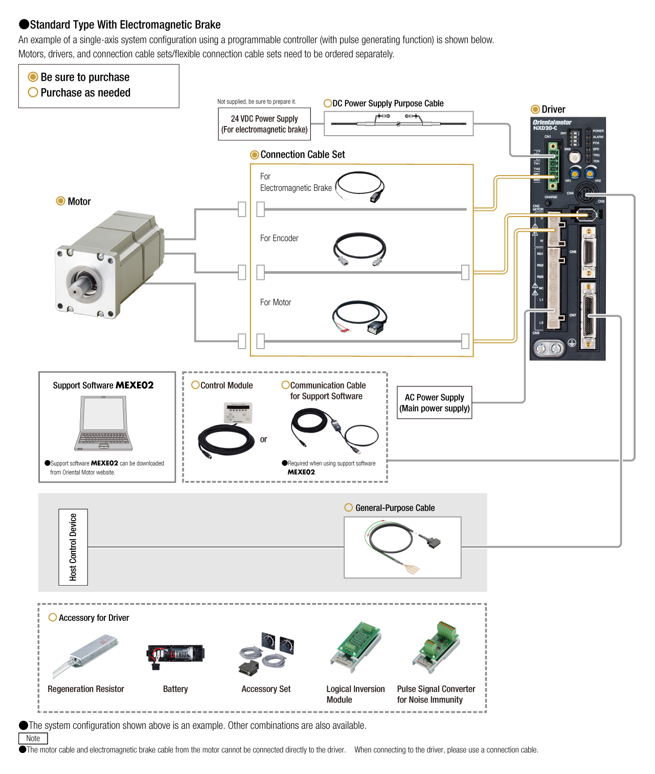
Cáp và phụ kiện