Stepper Motors PKP Series/CVD Series Pulse Input Driver
PKP203D06B+CVD206BR-K
Motor
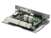
Control Circuit
| Phân loại sản phẩm | Tên sản phẩm | Giá niêm yết | Giá niêm yết | Ngày vận chuyển |
|---|---|---|---|---|
| Motor | PKP203D06B | - | - | Sản phẩm dự kiến ngừng sản xuất (30.6.2025 Đơn hàng cuối cùng) |
| Control Circuit | CVD206BR-K | SGD 171 | USD 137 | 5 Working days |
- *Vui lòng liên hệ với chúng tôi về việc mua sản phẩm.
- *Sản phẩm sẽ ngừng sản xuất vào ngày 29.8.2025. Vui lòng đặt hàng trước thời hạn này.
Bao gồm
- Motor: None
Control Circuit: Connector Housing, Contact
Thông số kỹ thuật
Đặc trưng
Kích thước
Tải dữ liệu
Các thông số kỹ thuật khác
General Specifications (Motor)
| Specifications | Motor | |
|---|---|---|
| Thermal Class | 130 (B) | |
| Insulation Resistance | The measured value is 100 MΩ min. when a 500 VDC megger is applied (PKP203 100 VDC megger) between the coil and the case of the motor under normal ambient temperature and humidity. | |
| Dielectric Strength |
No abnormalities are observed, even when applying voltage between the coil and the case of the motor for 1 minute under normal ambient temperature and humidity with the following conditions.
|
|
| Operating Environment (when operating) |
Ambient Temperature | -10~+50 °C (Non-freezing) Flat Type Harmonic Gearhead is 0~+40 °C (Non-freezing) |
| Ambient Humidity | 85 % max. (Non-condensing) | |
| Atmosphere | No corrosive gases or dust No exposure to water, oil or other liquids. | |
| Temperature Rise | Winding temperature rise 80 °C max. (Based on Oriental Motor's internal measurement conditions) | |
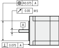
| Stop position accuracy*1 | ±3 arc minute (±0.05˚) [PKP21□, PKP242, PKP262is ±5 arcmin (±0.083°), PK26□J, PK26□JDis ±2 arcmin (±0.034°)] |
|
| Shaft Runout | 0.05 T.I.R. (mm) *4 *5 | |
| Radial Play*2 | 0.025 mm Max. (Load 5 N) [PKP203 Load 2.5 N] |
|
| Axial Play*3 | 0.075 mm Max (Load 10 N) [PKP203・PKP21□ Load 1 N, PKP22□, PKP242, PKP262 Load 2.5 N] |
|
| Concentricity of Installation Pilot to the Shaft | 0.075 T.I.R. (mm)*4 | |
| Perpendicularity of mounting surface to the shaft | 0.075 T.I.R. (mm)*4 | |
- *1
- This is the value at full step and no load (Varies depending on the size of the load).
- *2
- Radial Play: Displacement in shaft position in the radial direction when a 5 N load (PKP203 Load 2.5 N) is applied perpendicular to the tip of the motor shaft.
- *3
- Axial Play: Displacement in shaft position in the axial direction when a 10 N load (PKP203, PKP21□ Load 1 N, PKP22□, PKP242, PKP262 Load 2.5 N) is applied to the motor shaft in the axial direction.
- *4
- T.I.R. (Total Indicator Reading): The total dial gauge reading when the measurement section is rotated 1 revolution centered on the reference axis center.
- *5
- PKP244P has 0.025 T.I.R. (mm)
Note
- Disconnect the motor and driver when measuring insulation resistance, or conducting a dielectric strength test.
Also, do not conduct these tests on the motor encoder section.
Permissible Radial Load and Permissible Axial Load
| Type | Motor Frame Size |
Motor Product Name | Gear Ratio | Permissible Radial Load | Permissible Axial Load |
||||
|---|---|---|---|---|---|---|---|---|---|
| Distance From Shaft End [mm] | |||||||||
| 0 | 5 | 10 | 15 | 20 | |||||
| Standard Type | 13 mm | PKP203 | - | 5 | 6 | - | - | - | 1 |
| 20 mm | PKP213, PKP214 | 12 | 15 | - | - | - | 3 | ||
| 28 mm | PKP223, PKP225 | 25 | 34 | 52 | - | - | 5 | ||
| 35 mm | PKP233, PKP235 | 20 | 25 | 34 | 52 | - | 10 | ||
| 42 mm | PKP243, PKP244, PKP245, PKP246 | 20 | 25 | 34 | 52 | - | 10 | ||
| PKP243□2, PKP244□2, PKP245□2, PKP246□2 | 35 | 44 | 58 | 85 | - | 15 | |||
| 50 mm | PKP254, PKP256, PKP258 | 61 | 73 | 90 | 110 | - | 20 | ||
| 56.4 mm | PKP264, PKP266, PKP268 | 61 | 73 | 90 | 110 | 160 | 20 | ||
| PKP264□2, PKP266□2, PKP268□2 | 90 | 100 | 130 | 180 | 270 | 30 | |||
| 60 mm | PK264J, PK266J, PK267J, PK269J | 50 | 60 | 75 | 100 | 150 | 20 | ||
| 85 mm | PKP296, PKP299, PKP2913 | 260 | 290 | 340 | 390 | 480 | 60 | ||
| High-Torque Type | 42 mm | PKP244 | - | 90 | 100 | 130 | 180 | - | 15 |
| High-Resolution Type | 28 mm | PKP223, PKP225 | - | 25 | 34 | 52 | - | - | 5 |
| 42 mm | PKP243, PKP244 | 20 | 25 | 34 | 52 | - | 10 | ||
| PKP243□2, PKP244□2, PKP245□2, PKP246□2 | 35 | 44 | 58 | 85 | - | 15 | |||
| 56.4 mm | PKP264, PKP266, PKP268 | 61 | 73 | 90 | 110 | 160 | 20 | ||
| PKP264□2, PKP266□2, PKP268□2 | 90 | 100 | 130 | 180 | 270 | 30 | |||
| Flat Type Standard |
42 mm | PKP242 | - | 20 | 25 | 34 | - | - | 5 |
| 60 mm | PKP262 | ||||||||
| Flat Type With Harmonic Gearheads |
51 mm | PKP242 | 50, 100 | - | - | - | - | - | 200 |
| 61 mm | PKP262 | 450 | |||||||
| SH geared type | 28 mm | PKP223 | 7.2, 9, 10, 18, 36 | 15 | 17 | 20 | 23 | - | 10 |
| 42 mm | PKP243 | 3.6, 7.2, 9, 10, 18, 36 | 10 | 15 | 20 | 30 | - | 15 | |
| 60 mm | PKP264 | 3.6, 7.2, 9, 10 | 30 | 40 | 50 | 60 | 70 | 30 | |
| 18, 36 | 80 | 100 | 120 | 140 | 160 | ||||
| 90 mm | PK296 | 3.6, 7.2, 9, 10, 18, 36 | 220 | 250 | 300 | 350 | 400 | 100 | |
| CS Geared Type | 28 mm | PKP223 | 10, 15, 20 | 30 | 37 | 50 | 73 | - | 30 |
| 42 mm | PKP243 | 5, 10, 15, 20 | 59 | 68 | 80 | 96 | - | 40 | |
| 60 mm | PKP264 | 160 | 170 | 200 | 220 | 260 | 70 | ||

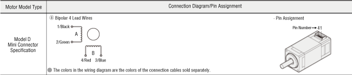
Inner Wiring Diagram of Motor
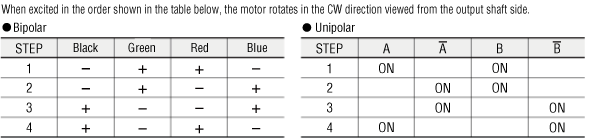
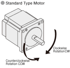
Rotation Direction
Geared Motor Rotation Direction
This indicates the rotation direction when viewed from the output shaft side.
The rotation direction of the gearhead output shaft relative to the standard type motor output shaft varies depending on the gear type and gear ratio. Please check the following table.
| Type | Gear Ratio | Rotation Direction as Viewed From the Motor Output Shaft Side |
|---|---|---|
| TS Geared Type | 3.6, 7.2, 10 | Same direction |
| 20, 30 | Opposite direction | |
| TH Geared Type Frame size 28 mm |
7.2, 10 | Opposite direction |
| 20, 30 | Same direction | |
| TH Geared Type Frame size 42 mm, 60 mm, 90 mm |
3.6, 7.2, 10 | Same direction |
| 20, 30 | Opposite direction | |
| SH Geared Type Frame size 28 mm |
7.2, 36 | Same direction |
| 9, 10, 18 | Opposite direction | |
| SH Geared Type Frame size 42 mm, 60 mm |
3.6, 7.2, 9, 10 | Same direction |
| 18, 36 | Opposite direction | |
| SH Geared Type Frame size 90 mm |
3.6, 7.2, 9, 10, 18 | Same direction |
| 36 | Opposite direction | |
| CS Geared Type | 5, 10, 15, 20 | Same direction |
|
FC Geared Type PS Geared Type PN Geared Type HPG Geared Type |
Overall gear ratio | Same direction |
| Harmonic Geared Type | 50, 100 | Opposite direction |
Circuit General Specifications
| Item | Specifications | |
|---|---|---|
| Operating Environment (In operation) | Ambient Temperature | 0∼+50 °C (Non-freezing) |
| Ambient Humidity | 85 % max. (Non-condensing) | |
| Atmosphere | No corrosive gases or dust. No exposure to water, oil or other liquids. | |
Circuit Specifications
| Maximum Input Pulse Frequency |
Line driver output by host controller: 1 MHz (at 50 % duty) Open-Collector Output by Host Controller: 250 kHz (at 50 % duty) Negative logic pulse input |
|---|---|
| Input Signals |
|
| Output Signals |
Photocoupler and open-collector output (ALM, TIM) External Use Conditions: 30 VDC max., 10 mA max. |
Tiêu chuẩn
[Motor Section]
Hazardous Substances
The product does not contain any substances (10 substances) exceeding the regulation values of the RoHS Directive (2011/65/EU, 2015/863/EU).
[Circuit Section]
Regulations and Standards Materials
Documents about compliance with regulations and standards can be downloaded from the "Data Download" tab on the product details page.
(The types of files available for download vary by product.)
Explanations of the Global Laws, Regulations and Standards can be found here.
Information about our compliance with regulations and standards for each of our product series can be found here.
Hazardous Substances
The product does not contain any substances (10 substances) exceeding the regulation values of the RoHS Directive (2011/65/EU, 2015/863/EU).
Cấu hình hệ thống
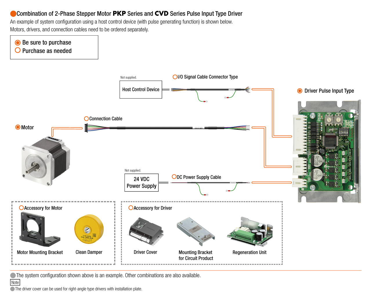
Cáp và phụ kiện