What is the Difference Between an Open Collector and a Line Driver?


-

Ms. Ori, please help me.
-

What's wrong, Vex? With a pathetic voice.
-

A customer asked me if we have a product that can combine pulse output with the programmable controller's line driver output. But I've only heard open-collector output…
-

I've been hearing about this a lot lately.
-

Really?
-

Yes. So Vex, first, can you explain what an open-collector output is?
-

Of course!
This method connects the output transistor on the programmable controller to the input photocoupler on the driver side and controls ON/OFF of the input photocoupler by turning the transistor ON/OFF.
Basically, about 10 mA of current flows through the photocoupler and if that amount of current is reached, it allows for operations over a wide range of voltages, from 5~24 VDC! Right?When the photocoupler is OFF 
When the photocoupler is ON 
-

Yes! Perfect.
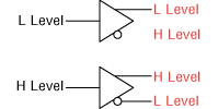
Then, line driver output will look like the figure below.
The output terminals of each line driver output are inverted between high and low levels when outputting pulses.Line driver output image 
Let's look at the current flow when the programmable controller's line driver output is connected to the photocoupler input on the driver side.
Current flows from the High level to the Low level, so if we switch the High level and the Low level on the line driver output, the current will flow in alternate directions.When the photocoupler is OFF 
When the photocoupler is ON 
However, since the direction of the current flowing through the photocoupler is fixed, it is possible to control the ON/OFF of the photocoupler depending on the direction which the current flows.
-

I see!! I understand the difference. But is there any benefit to using line driver output?
-

Good point. Check the specifications of the driver part of the servo motor NX Series in the catalog.
Driver Specifications
Maximum input Line Driver Output by Programmable Controller: 500 kHz (at 50 % duty) Pulse frequency Open-Collector Output by Programmable Controller: 250 kHz (at 50 % duty) If we look at the maximum input pulse frequency, we see that line driver output can handle up to twice the frequency.
The latest servo motors and stepper motors allow for very precise resolution settings. For example, at half the resolution, the number of rotations in the motor is also halved, so if the resolution becomes even finer, a higher pulse frequency is required.
Some customers use this method for the reasons like noise resistance or to extend the pulse line. -

I understand very well.
-

By the way, do you know what products are compatible with line driver output?
-

I remember seeing the αSTEP AR series in a catalog... were there any others?
-

If you look at the wiring diagrams and driver specifications I just spoke about, you'll understand right?
-

Um…
αSTEP: AZ Series and AR Series
Servo motors: NX Series
These are the one. -

That’s right. Just make sure to remember those!
By the way, what kind of products is your customer looking for this time? -

If I remember correctly…they were looking for a servo motor.
-

Then you can introduce them with confidence, right?
-

Yes!! I'll go to introduce the NX Series.
- February 17, 2021 Updated with the latest information.

