Brushless Motors BLE Series CC-Link Ver.1.1 Compatible
BLEM512-GFS+GFS5G10+BLED12C-CC


| Phân loại sản phẩm | Tên sản phẩm | Giá niêm yết | Giá niêm yết | Ngày vận chuyển |
|---|---|---|---|---|
| Motor | BLEM512-GFS | SGD 250 | USD 200 | 40 Working Days |
| Gearhead | GFS5G10 | SGD 183 | USD 146 | 3 Working Days |
| Control Circuit | BLED12C-CC | SGD 571 | USD 457 | 50 Working Days |
Bao gồm
- Motor: None
Gearhead: Mounting Screws, Parallel Key
Control Circuit: User I/O Connector, CC-Link-Compatible Connector
Thông số kỹ thuật
Đặc trưng

Speed - Torque Characteristics
Kích thước
Motor/Gearhead
Control Circuit
Connection Cable (When Selected)
Tải dữ liệu
Các thông số kỹ thuật khác
Common Specifications
| Item | Specifications |
|---|---|
| Speed Setting Methods | CC-Link communication or setting by control module and support software |
| Acceleration Time and Deceleration Time | 0.2∼15s CC-Link communication or setting by control module and support software |
| Input Signals | Photocoupler Input Input resistance: 4.7 kΩ External DC power supply 20.4~28.8 VDC Current 100 mA min. |
| Output Signals | Open-Collector Output External Usage Conditions 4.5~30.0 VDC Current 40 mA max. |
| Protective Functions | Overcurrent, overload, overvoltage, main power supply off, undervoltage, sensor error, main circuit output error, overload, over speed, EEPROM error, sensor error at power-on, prevention of operation at power-on, regeneration resistor overheat, external stop, network bus error |
| Maximum Extension Distance | 20.4 m between motor and driver |
| Time Rating | Continuous |
Note
- This product cannot conduct speed control of the motor in applications in which the motor side is turned from the load side, such as gravitational operation.
When a load exceeding the permissible load inertia value is driven, or when gravitational operation is performed, the overvoltage protective function works to bring the motor to a coasting stop.
General Specifications
| Item | Motor | Driver | |
|---|---|---|---|
| Insulation Resistance | 100 MΩ or more when a 500 VDC megger is applied between the windings and the case after continuous operation under normal ambient temperature and humidity. |
After continuous operation at normal ambient temperature and humidity, the measurement value between the power supply terminal and the protective earth terminal and the power supply terminal and the I/O terminal is 100 MΩ min. using a 500 VDC megger. |
|
| Dielectric Strength | No abnormality is observed even with an application of 1.5 kVAC at 50 Hz between the coils and the case for 1 minute after continuous operation at normal ambient temperature and humidity. |
No abnormality is observed even with an application of 1.5 kVAC at 50 Hz between the power supply terminal and the protective earth terminal or 1.5 kVAC at 50 Hz between the power supply terminal and the signal I/O terminal for 1 minute after continuous operation at normal ambient temperature and humidity. |
|
| Temperature Rise | After continuous operation at normal ambient temperature and humidity, the measured value using the thermocouple method is 50 °Cmax. for the temperature rise of the coils and 40 °C max. *1 for the temperature rise on the case surface. |
After continuous operation at normal ambient temperature and humidity, the measurement value of the temperature rise of the heat sink is 50 °C max. using the thermocouple method. |
|
| Operating Environment | Ambient Temperature | 0∼+50°C (Non-freezing) | |
| Ambient Humidity | 85 % max. (Non-condensing) | ||
| Altitude | Up to 1000 m above sea level | ||
| Atmosphere | No corrosive gases or dust Cannot be used in a radioactive area, magnetic field, vacuum, or other special environments. | ||
| Vibration | Not subject to continuous vibration or excessive shock In conformance with JIS C 60068-2-6, "Sine-wave vibration test method" Frequency Range: 10~55 Hz, Half Amplitude: 0.15 mm, Sweep Direction: 3 directions (X, Y, Z), Number of Sweeps: 20 times |
||
| Storage Conditions*2 | Ambient Temperature | -25~+70°C (Non-freezing) | |
| Ambient Humidity | 85 % max. (Non-condensing) | ||
| Altitude | Up to 3000 m above sea level | ||
| Thermal Class | UL/CSA Standards: 105 (A), EN Standards: 120 (E) | − | |
| Degree of Protection | IP54 (Excluding the installation surface of the round shaft type and connectors) | IP20 | |
- *1
- Attach round shaft types to a heat sink (Material: aluminum) of one of the following sizes to maintain a motor case surface temperature of 90 °C max.
30 W Type: 115x115 mm, 5 mm thickness
60 W Type: 135x135 mm, 5 mm thickness
120 W Type: 165x165mm, 5mm thickness - *2
- The value for storage condition applies to short periods such as the period during transport.
Note
- Do not measure insulation resistance or perform a dielectric strength test the motor and driver are connected.
CC-Link Communication Specifications
| Communication Protocol | CC-Link Ver.1.10 |
|---|---|
| Station Type | Remote Device Station |
| Number of Occupied Stations | 1 Station Occupied |
| Transmission Rate | 156 kbps/625 kbps/2.5 Mbps/5 Mbps/10 Mbps |
| Maximum Transmission Distance | Varies depending on transmission rate |
| Maximum Number of Connected Units | 42 units The maximum number of connected units depends on the configuration of the CC-Link system used. For details, conduct confirmation of the specifications of the CC-Link system master (or local) device. |
| Communication Cable | CC-Link Dedicated Cable |
| Connector | Phoenix Contact Corporation MVSTBW2,5/5-STF-5,08AU |
Permissible Radial Load and Permissible Axial Load
Combination type with a parallel shaft gearhead
| Product Name | Gear Ratio | Permissible Radial Load | Permissible Axial Load N |
||
|---|---|---|---|---|---|
| From Shaft End 10 mm N |
From Shaft End 20 mm N |
||||
| BLE23■C□S◇ | 5 | At 80~3000 r/min | 100 | 150 | 40 |
| At 4000 r/min | 90 | 110 | |||
| 10, 15, 20 | At 80~3000 r/min | 150 | 200 | ||
| At 4000 r/min | 130 | 170 | |||
| 30, 50, 100, 200 | At 80~3000 r/min | 200 | 300 | ||
| At 4000 r/min | 180 | 230 | |||
| BLE46■C□S◇ | 5 | At 80~3000 r/min | 200 | 250 | 100 |
| At 4000 r/min | 180 | 220 | |||
| 10, 15, 20 | At 80~3000 r/min | 300 | 350 | ||
| At 4000 r/min | 270 | 330 | |||
| 30, 50, 100, 200 | At 80~3000 r/min | 450 | 550 | ||
| At 4000 r/min | 420 | 500 | |||
| BLE512■C□S◇ | 5 | At 80~3000 r/min | 300 | 400 | 150 |
| At 4000 r/min | 230 | 300 | |||
| 10, 15, 20 | At 80~3000 r/min | 400 | 500 | ||
| At 4000 r/min | 370 | 430 | |||
| 30, 50, 100, 200 | At 80~3000 r/min | 500 | 650 | ||
| At 4000 r/min | 450 | 550 | |||
Combination type with a hollow shaft flat gearhead
| Product Name | Gear Ratio | Permissible Radial Load | Permissible Axial Load N |
||
|---|---|---|---|---|---|
| From Shaft End 10 mm N |
From Shaft End 20 mm N |
||||
| BLE23■C□F◇ | 5, 10 | At 80~3000 r/min | 450 | 370 | 200 |
| At 4000 r/min | 410 | 330 | |||
| 15, 20, 30, 50, 100, 200 |
At 80~3000 r/min | 500 | 400 | ||
| At 4000 r/min | 460 | 370 | |||
| BLE46■C□F◇ | 5, 10 | At 80~3000 r/min | 800 | 660 | 400 |
| At 4000 r/min | 730 | 600 | |||
| 15, 20, 30, 50, 100, 200 |
At 80~3000 r/min | 1200 | 1000 | ||
| At 4000 r/min | 1100 | 910 | |||
| BLE512■C□F◇ | 5, 10 | At 80~3000 r/min | 900 | 770 | 500 |
| At 4000 r/min | 820 | 700 | |||
| 15, 20 | At 80~3000 r/min | 1300 | 1110 | ||
| At 4000 r/min | 1200 | 1020 | |||
| 30, 50, 100, 200 | At 80~3000 r/min | 1500 | 1280 | ||
| At 4000 r/min | 1400 | 1200 | |||
Round Shaft Type
| Product Name | Permissible Radial Load | Permissible Axial Load | |
|---|---|---|---|
| 10 mm From Shaft End N |
20 mm From Shaft End N |
||
| BLE23■CA◇ | 80 | 100 | Half of the motor mass or less |
| BLE46■CA◇ | 110 | 130 | |
| BLE512■CA◇ | 150 | 170 | |
Tiêu chuẩn
Regulations and Standards Materials
Documents about compliance with regulations and standards can be downloaded from the "Data Download" tab on the product details page.
(The types of files available for download vary by product.)
Explanations of the Global Laws, Regulations and Standards can be found here.
Information about our compliance with safety standards for each of our product models can be found here.
Hazardous Substances
The product does not contain any substances (10 substances) exceeding the regulation values of the RoHS Directive (2011/65/EU, 2015/863/EU).
Cấu hình hệ thống
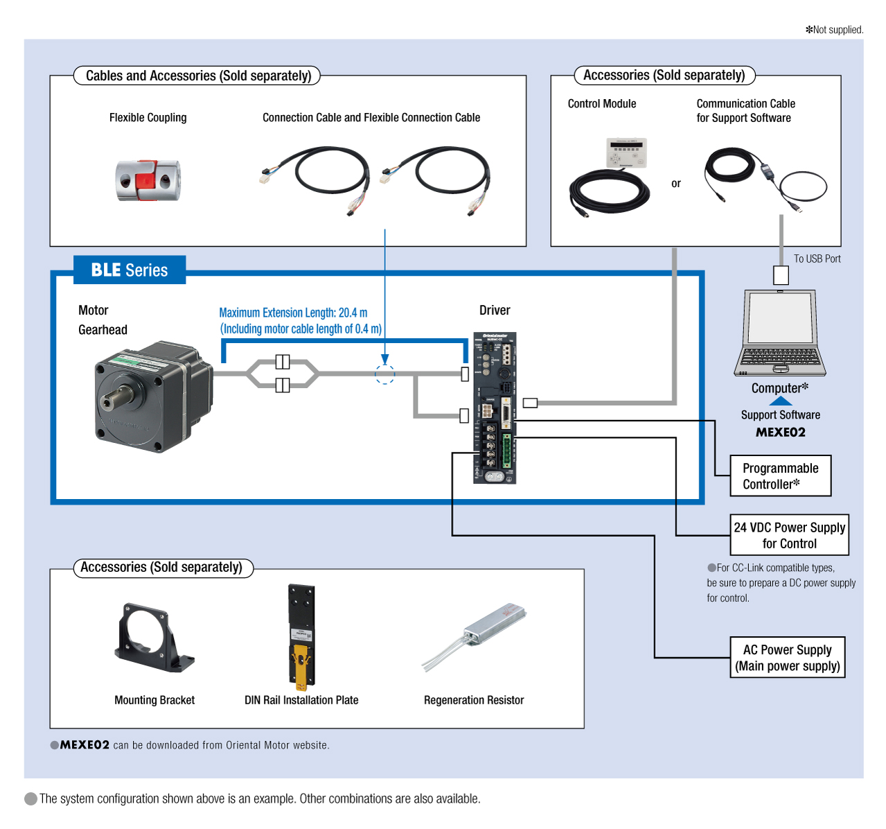
Cáp và phụ kiện
close
close
close
close