Brushless Motors BLE2 Series
BLM6200SHPM-GFV+GFV6G30S+BLE2D200-CM

| Phân loại sản phẩm | Tên sản phẩm | Giá niêm yết | Giá niêm yết | Ngày vận chuyển |
|---|---|---|---|---|
| Motor | BLM6200SHPM-GFV | SGD 544 | USD 435 | 11 Working Days |
| Gearhead | GFV6G30S | SGD 275 | USD 220 | 3 Working Days |
| Control Circuit | BLE2D200-CM | SGD 354 | USD 283 | 11 Working Days |
Bao gồm
- Motor: None
Gearhead: Mounting Screws, Parallel Key
Control Circuit: None
Thông số kỹ thuật
Đặc trưng
Speed - Torque Characteristics
Kích thước
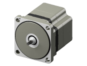
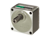
Motor/Gearhead
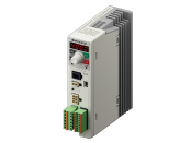
Control Circuit
Connection Cable (When Selected)
Tải dữ liệu
Các thông số kỹ thuật khác
Common Specifications
| Item | Specifications | |
|---|---|---|
| Speed Setting Methods | Digital setting |
|
| Analog Setting |
|
|
| Acceleration Time and Deceleration Time | Setting Range | 0.0~15.0 s (Factory Setting: 0.5 s) |
| Setting Method |
|
|
| Torque Limiting *1 | Setting Range | 0~300% (Factory Setting: 300%) |
| Digital setting |
|
|
| Analog Setting |
|
|
| Operation Data Setting Number | 16 points max. (Factory Setting: 4 points) | |
| Input Signals | Photocoupler Input Input Resistance: 6.6 kΩ Connectable External DC Power Supply: 24 VDC −15∼+20% Current 100 mA min. Sink Input/Source Input Supported through external wiring |
|
| Arbitrary signal assignment to IN0∼IN6 input (7 points) is possible. [ ]: Initial setting [FWD], [REV], [STOP-MODE], [M0], [M1], [ALARM-RESET], [MB-FREE]. *2, M2, M3, H-FREE, TL, INFO-CLR, HMI, EXT-ERROR, START/STOP *3, RUN/BRAKE *3, CW/CCW *3 |
||
| Output Signals | Photocoupler and Open-Collector Output (ON Power Supply: maximum 1.6 V) External power supply: 4.5~30 VDC, 100 mA max. (5 mA min. for SPEED-OUT output) Sink output/Source output Supported through external wiring |
|
| Arbitrary signal assignment to OUT0, OUT1 output (2 points) is possible. [ ]: Initial setting [SPEED-OUT], [ALARM-OUT], MOVE, INFO, TLC, VA, DIR |
||
| Protective Function | When the following protective function are activated, the ALARM-OUT output will turn OFF, The motor will stop. At the same time, the alarm code will be displayed and the ALARM LED will blink red. (In the case of an electromagnetic brake motor, the motor shaft will be retained.) Overcurrent, main circuit overheat, overvoltage, undervoltage, sensor error, overload, over-speed, EEPROM error, initial sensor error, prevention of operation at power-on, external stop |
|
| Information | When information is generated, the INFO output turns ON and the ALARM LED blinks orange. The motor will continue to operate. |
|
| Maximum Extension Distance | 20.5 m between motor and driver [when using connection cable (for relay; sold separately)] | |
| Time Rating | Continuous | |
- *1
- The torque limiting will cause an error with a maximum of ±10 % (at rated torque and rated speed) between the setting value and the generated torque, depending on the setting speed, power supply voltage, and motor cable extension distance.
- *2
- If it is not equipped with an electromagnetic brake, it will be [unused].
- *3
- Can be used when 3-wire input mode is selected.
General Specifications
| Item | Motor | Driver | |
|---|---|---|---|
| Insulation Resistance | 100 MΩ or more when a 500 VDC megger is applied between the windings and the case after continuous operation under normal ambient temperature and humidity. |
After continuous operation at normal ambient temperature and humidity, the value measured with a 500 VDC megger between the power supply terminal and the protective earth terminal, and between the power supply terminal and the I/O signal terminal is 100 MΩ min. |
|
| Dielectric Strength | No abnormality is observed even with an application of 1.5 kVAC at 50 Hz between the coils and the case for 1 minute after continuous operation at normal ambient temperature and humidity. |
After continuous operation at normal ambient temperature and humidity, no abnormality is observed even if 50 Hz, 1.5 kVAC is applied between the power supply terminal and the protective earth terminal, and 50 Hz, 1.5 kVAC is applied between the power supply terminal and the I/O signal terminal for 1 minute. |
|
| Temperature Rise | After rated continuous operation at normal ambient temperature and humidity, the temperature rise of the coils measured by the thermocouple method is max. 50°C (max. 60 °C for 300 W and 400 W), and the measured value of the temperature rise of the case surface is max. 40°C (max. 50 °C for 300 W and 400 W)*1. |
After continuous operation at normal ambient temperature and humidity, the measurement value of the temperature rise of the heat sink is 50 °C max. using the thermocouple method. |
|
| Operating Environment*2 | Ambient Temperature | 0∼+40 °C (Non-freezing) | 0~+50°C*3 (Non-freezing) |
| Ambient Humidity | 85 % max. (Non-condensing) | ||
| Altitude | Up to 1000 m above sea level | ||
| Atmosphere | No corrosive gases or dust Should not be exposed to oil. Cannot be used in a radioactive area, magnetic field, vacuum, or other special environments. |
||
| Vibration | Must not be subjected to continuous vibration or excessive shock. Conforms to JIS C 60068-2-6, "Sine-wave vibration test Method." Frequency Range: 10~55 Hz, Half Amplitude: 0.15 mm Sweep direction: 3 directions (X, Y, Z) Number of sweeps: 20 |
||
| Storage Conditions*4 | Ambient Temperature | -20~+70 °C (Non-freezing) JH Gearhead, JB Gearhead, JV Gearhead: -10~+60°C (Non-freezing) |
-25~+70°C (Non-freezing) |
| Ambient Humidity | 85 % max. (Non-condensing) | ||
| Altitude | Up to 3000 m above sea level JH Gearhead, JB Gearhead, JV Gearhead: Up to 1000 m above sea level |
||
| Atmosphere | No corrosive gases or dust Should not be exposed to water or oil. Cannot be used in a radioactive area, magnetic field, vacuum, or other special environments. |
||
| Thermal Class | UL/CSA Standards: 105 (A) EN Standards: 120 (E) |
− | |
| Degree of Protection *5 | Dustproof and Waterproof Specifications (GFV Gearhead): IP67 GFV Gearhead, JH Gearhead, JV Gearhead, Round Shaft: IP66 (Excluding mounting surface of the round shaft type.) FR Gearhead: IP65 JB Gearhead: IP44 |
IP20) | |
- *1
- Attach round shaft types to a heat sink (Material: aluminum) of one of the following sizes to maintain a motor case surface temperature of 90 °C max.
30 W Type: 115x115 mm, 5 mm thickness, 60 W Type: 135x135 mm, 5 mm thickness
120 W Type: 165x165 mm, 5 mm thickness, 200 W Type: 200x200 mm, 5 mm thickness, 300 W, 400 W Type: 250x250 mm, 6 mm thickness - *2
- Install the driver to a location that has the same heat radiation capability as an aluminum metal plate.
Single Mounting 200 x 200 mm, 2 mm thickness
Close Mounting 350x350 mm, 2 mm thickness - *3
- For close mounting (200 W, 300 W, and 400 W only) and DIN rail mounting, the temperature range is 0~+40 °C.
- *4
- The value for storage condition applies to short periods such as the period during transport.
- *5
- The IP indication that shows the watertight and dust-resistant performance are specified under IEC 60529 and IEC 60034-5.
The degree of protection is when the connection cable is connected. The connector for driver connection is excluded.
Note
- Do not measure insulation resistance or perform a dielectric strength test the motor and driver are connected.
Permissible Radial Load and Permissible Axial Load
Parallel Shaft Gearhead
| Output | Gear Ratio | Permissible Radial Load | Permissible Axial Load N |
||
|---|---|---|---|---|---|
| 10 mm From the End of the Output Shaft N |
20 mm From the End of the Output Shaft N |
||||
| 30 W | 5 | At 80~3000 r/min | 100 | 150 | 40 |
| At 4000 r/min | 90 | 110 | |||
| 10, 15, 20 | At 80~3000 r/min | 150 | 200 | ||
| At 4000 r/min | 130 | 170 | |||
| 30, 50, 100, 200 | At 80~3000 r/min | 200 | 300 | ||
| At 4000 r/min | 180 | 230 | |||
| 60 W | 5 | At 80~3000 r/min | 200 | 250 | 100 |
| At 4000 r/min | 180 | 220 | |||
| 10, 15, 20 | At 80~3000 r/min | 300 | 350 | ||
| At 4000 r/min | 270 | 330 | |||
| 30, 50, 100, 200 | At 80~3000 r/min | 450 | 550 | ||
| At 4000 r/min | 420 | 500 | |||
| 120 W | 5 | At 80~3000 r/min | 300 | 400 | 150 |
| At 4000 r/min | 230 | 300 | |||
| 10, 15, 20 | At 80~3000 r/min | 400 | 500 | ||
| At 4000 r/min | 370 | 430 | |||
| 30, 50, 100, 200 | At 80~3000 r/min | 500 | 650 | ||
| At 4000 r/min | 450 | 550 | |||
| 200 W 300 W 400 W |
5, 10, 15, 20 | At 80~3000 r/min | 550 | 800 | 200 |
| At 4000 r/min | 500 | 700 | |||
| 30, 50 | At 80~3000 r/min | 1000 | 1250 | 300 | |
| At 4000 r/min | 900 | 1100 | |||
| 100 | At 80~3000 r/min | 1400 | 1700 | 400 | |
| At 4000 r/min | 1200 | 1400 | |||
Hollow Shaft Flat Gearhead
| Output | Gear Ratio | Permissible Radial Load | Permissible Axial Load N |
||
|---|---|---|---|---|---|
| 10 mm From Mounting Surface N |
20 mm From Mounting Surface N |
||||
| 30 W | 5, 10 | At 80~3000 r/min | 450 | 370 | 200 |
| At 4000 r/min | 410 | 330 | |||
| 15, 20, 30, 50, 100, 200 |
At 80~3000 r/min | 500 | 400 | ||
| At 4000 r/min | 460 | 370 | |||
| 60 W | 5, 10 | At 80~3000 r/min | 800 | 660 | 400 |
| At 4000 r/min | 730 | 600 | |||
| 15, 20, 30, 50, 100, 200 |
At 80~3000 r/min | 1200 | 1000 | ||
| At 4000 r/min | 1100 | 910 | |||
| 120 W | 5, 10 | At 80~3000 r/min | 900 | 770 | 500 |
| At 4000 r/min | 820 | 700 | |||
| 15, 20 | At 80~3000 r/min | 1300 | 1110 | ||
| At 4000 r/min | 1200 | 1020 | |||
| 30, 50, 100, 200 | At 80~3000 r/min | 1500 | 1280 | ||
| At 4000 r/min | 1400 | 1200 | |||
| 200 W 300 W 400 W |
5*, 10 | At 80~3000 r/min | 1230 | 1070 | 800 |
| At 4000 r/min | 1130 | 990 | |||
| 15, 20 | At 80~3000 r/min | 1680 | 1470 | ||
| At 4000 r/min | 1550 | 1360 | |||
| 30, 50, 100 | At 80~3000 r/min | 2040 | 1780 | ||
| At 4000 r/min | 1900 | 1660 | |||
- *400W Type only
About Load Position
Round Shaft Type
| Output | Permissible Radial Load | Permissible Axial Load N |
|
|---|---|---|---|
| 10 mm From the End of the Output Shaft N |
20 mm From the End of the Output Shaft N |
||
| 30 W 60 W |
80 | 100 | 20 |
| 120 W 200 W 300 W 400 W |
150 | 170 | 25 |
Permissible Radial Load Calculation
The formula for calculating the permissible radial load varies depending on the mechanism.
When One Side of the Load Shaft is Not Supported by the Bearing Unit
The radial load is the most difficult mechanism. A Stepped Type Load Shaft is recommended.
| Product Name | Permissible Radial Load W [N] |
|---|---|
| GFS2G□FR |
\(\begin{align} \mathrm{W} [\mathrm{N}] = \frac{36}{36 + \mathrm{Lp}} \times \mathrm{F}_0 [\mathrm{N}] \end{align}\)
|
| GFS4G□FR |
\(\begin{align} \mathrm{W} [\mathrm{N}] = \frac{40}{40 + \mathrm{Lp}} \times \mathrm{F}_0 [\mathrm{N}] \end{align}\)
|
| GFS5G□FR |
\(\begin{align} \mathrm{W} [\mathrm{N}] = \frac{50}{50 + \mathrm{Lp}} \times \mathrm{F}_0 [\mathrm{N}] \end{align}\)
|
| GFS6G□FR |
\(\begin{align} \mathrm{W} [\mathrm{N}] = \frac{60}{60 + \mathrm{Lp}} \times \mathrm{F}_0 [\mathrm{N}] \end{align}\)
|
When One Side of the Load Shaft is Supported by the Bearing Unit
| Product Name | Permissible Radial Load W [N] |
|---|---|
| GFS2G□FR GFS4G□FR GFS5G□FR GFS6G□FR |
\(\begin{align} \mathrm{W} [\mathrm{N}] = \frac{\mathrm{B}}{\mathrm{B} - \mathrm{Lp}} \times \mathrm{F}_0 [\mathrm{N}] \end{align}\)
|
| Product Name | Rotation Speed | Gear Ratio | F0 [N] |
|---|---|---|---|
| GFS2G□FR | At 80~3000 r/min | 5, 10 | 570 |
| 15~200 | 630 | ||
| At 4000 r/min | 5, 10 | 520 | |
| 15~200 | 580 | ||
| GFS4G□FR | At 80~3000 r/min | 5, 10 | 1000 |
| 15~200 | 1500 | ||
| At 4000 r/min | 5, 10 | 910 | |
| 15~200 | 1370 | ||
| GFS5G□FR | At 80~3000 r/min | 5, 10 | 1080 |
| 15, 20 | 1550 | ||
| 30~200 | 1800 | ||
| At 4000 r/min | 5, 10 | 980 | |
| 15, 20 | 1430 | ||
| 30~200 | 1680 | ||
| GFS6G□FR | At 80~3000 r/min | 5, 10 | 1430 |
| 15, 20 | 1960 | ||
| 30~100 | 2380 | ||
| At 4000 r/min | 5, 10 | 1320 | |
| 15, 20 | 1810 | ||
| 30~100 | 2210 |
Vertical Operation (Gravitational operation)
Vertical Drive (Gravitational Operation)
TheBLE2 Series achieves stable speed control during gravitational operation.
During vertical operation (gravitational operation), shown in the figure below, normally an external force causes the motor to rotate and function as a power generator. If this energy is applied to the driver, an error will occur.
The accessory regeneration resistor (sold separately) can convert regenerative energy into thermal energy for dissipation. Use the accessory regeneration resistor when using the motor for vertical operation or when braking a large inertial load quickly.
| Regeneration Resistor Product Name | Applicable Product | Continuous Regenerative Power | Instantaneous Regenerative Power |
|---|---|---|---|
| RGB100 | 30 W, 60 W 120W, 200W |
70 W | 720 W |
- Install the regeneration resistor in a place that has the same heat radiation capability as the heat sink (Material: aluminum 350×350 mm, 3 mm thickness).
Regenerative Power
The regenerative power can be estimated using the formula below. Use the calculated value as a reference.
Regenerative Power (W) = 0.1047 × TL [N·m] × N [r/min]
TL: Load Torque N: Rotation Speed
Gravitational Operation Capability
- Continuous gravitational operation exceeding the range of continuous regeneration resistor will trigger the built-in thermal protector (150°C).
- Use electromagnetic brake type for gravitational operation.
Tiêu chuẩn
Regulations and Standards Materials
Documents about compliance with regulations and standards can be downloaded from the "Data Download" tab on the product details page.
(The types of files available for download vary by product.)
Explanations of the Global Laws, Regulations and Standards can be found here.
Information about our compliance with safety standards for each of our product models can be found here.
Hazardous Substances
The product does not contain any substances (10 substances) exceeding the regulation values of the RoHS Directive (2011/65/EU, 2015/863/EU).
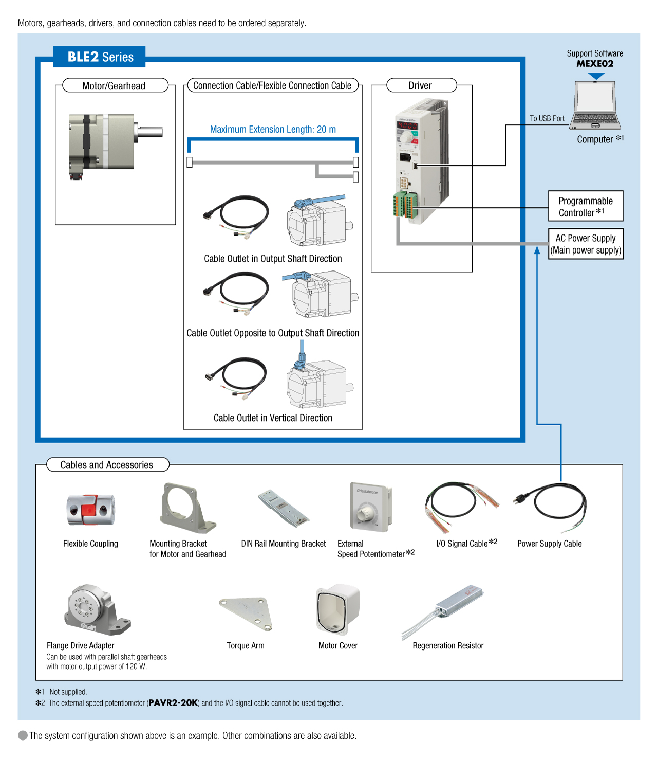
Cấu hình hệ thống