Stepper Motors CRK Series Pulse Input Type
CRK569APB
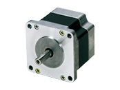
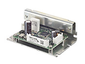
Motor/Control Circuit
| Phân loại sản phẩm | Tên sản phẩm | Giá niêm yết | Giá niêm yết | Ngày vận chuyển |
|---|---|---|---|---|
| Motor / Control Circuit | CRK569APB | SGD 461 | USD 369 | Sản phẩm dự kiến ngừng sản xuất (30.1.2026 Đơn hàng cuối cùng) |
- *Vui lòng liên hệ với chúng tôi về việc mua sản phẩm.
- *Sản phẩm sẽ ngừng sản xuất vào ngày 31.3.2026. Vui lòng đặt hàng trước thời hạn này.
Bao gồm
- Motor, Control Circuit, Connector Housing, Contact, Operating Manual
Thông số kỹ thuật
Kích thước
Control Circuit
Tải dữ liệu
Các thông số kỹ thuật khác
Driver Specifications
| Input Signal | Input Mode | Photocoupler input, Input resistance 220 Ω, Input current 7~20 mA Photocoupler "ON": +4.5~5.25 V, Photocoupler "OFF": 0~+1 V (voltage between terminals) |
|---|---|---|
| CW Pulse Signal (Pulse signal) |
CW direction operation command pulse signal (operation command pulse signal when in 1-pulse input mode), negative logic pulse input Pulse width is 1 μs min., rise and fall time is 2 μs max. Pulse duty 50 % Below When the pulse input is turned from "ON" to "OFF," the motor rotates 1 step. Maximum input pulse frequency 500 kHz (at 50 % pulse duty) |
|
| CCW Pulse Signal (Rotation direction signal) |
CCW directional motion command pulse signal (with 1-pulse input mode, rotation direction signal, Photocoupler "ON": CW, Photocoupler "OFF": CCW) Negative logic pulse input Pulse width 1 μs min. rise/fall time 2 μs max., pulse duty 50 % max. When the pulse input is turned from "ON" to "OFF," the motor rotates 1 step. Maximum Input Pulse Frequency 500 kHz (at 50 % pulse duty) |
|
| All Windings Off Signal | When the photocoupler is "ON," the output current to the motor is turned "OFF," and the motor shaft can be turned by external force. When the photocoupler is "OFF," output current to the motor is turned "ON." | |
| Step Angle Select Input Signal | When the photocoupler is "OFF," DATA1 is selected; when the photocoupler is "ON," DATA2 is selected. | |
| Current Cutback Release Signal | When the photocoupler is "ON," the automatic current cutback function is canceled at motor standstill. When the photocoupler is "OFF," the automatic current cutback function will be activated at motor standstill (after approx. 100 ms). | |
| Output Signal | Output Mode | Photocoupler and Open-Collector Output External Use Conditions: 24 VDC max., 10 mA max. |
| Excitation Timing Signal |
This signal is output when the excitation sequence is step "0." (Photocoupler "ON") Example)
0.72°/step (number of divisions - 1): Output once every 10 pulses
0.072°/step (number of divisions - 10): Output every 100 pulses |
|
| Function | Automatic current cutback, step angle switching, pulse input mode switching, smooth drive function, all windings off, excitation timing | |
| Cooling Method | Natural cooling method | |
General Specifications
| Specifications | Motor | Driver | |
|---|---|---|---|
| Thermal Class | 130 (B) [UL certified to 105 (A)] | − | |
| Insulation Resistance | Measurement value is 100 MΩ min. when a 500 VDC megger is applied between the windings and the case of the motor under normal ambient temperature and humidity. | − | |
| Dielectric Strength |
Under normal ambient temperature and humidity, no abnormalities were observed even at 1.5 kV * for 50 Hz and 60 Hz when applied between the coils and the case of the motor for 1 minute.
|
− | |
| Operating Environment (when operating) |
Ambient Temperature |
-10~+50 °C (Non-freezing):
Standard Type, High-Resolution Type, High-Torque Type
TH, PL, PS, PN geared type 0~+50 °C (Non-freezing):
PS Geared Type Φ22 mm
0~+40 °C (non-freezing):
Harmonic Geared Type
|
0~+40 °C (Non-freezing) |
| Ambient Humidity | 85 % max. (Non-condensing) | ||
| Atmosphere | No corrosive gases or dust. No exposure to water, oil or other liquids. | ||
| Temperature Rise | 5-phase excitation at rated current, winding temperature rise to 80 °C max. at standstill (resistance change method) | − | |
| Stop position accuracy*1 | ±3 arcmin (±0.05˚), CRK513P ±10 arcmin (±0.17˚) High-resolution type ±2 arcmin (±0.034˚) |
− | |
| Shaft Runout | 0.05 T.I.R. (mm)*4 | − | |
| Radial Play*2 | 0.025 mm Max. (Load 5 N) | − | |
| Axial Play*3 | 0.075 mm Max. (Load 10 N) [CRK513P Load 1 N, CRK52□ Load 2.5 N] |
− | |
| Concentricity of Installation Pilot to the Shaft | 0.075 T.I.R. (mm)*4 | − | |
| Perpendicularity of mounting surface to the shaft | 0.075 T.I.R. (mm)*4 | − | |
- *1
- This is the value at full step and no load (Varies depending on the size of the load).
- *2
- Radial Play: Displacement in shaft position in the radial direction when a 5 N load is applied perpendicular to the tip of the motor shaft.
- *3
- Axial Play: Displacement in shaft position in the axial direction when a 10 N load (CRK513P is 1 N, CRK52□ is 2.5 N) is applied to the motor shaft in the axial direction.
- *4
- T.I.R. (Total Indicator Reading): The total dial gauge reading when the measurement section is rotated 1 revolution centered on the reference axis center.
Note
- Do not measure insulation resistance or perform a dielectric strength test while the motor and driver are connected.
Rotation Direction
This indicates the rotation direction when viewed from the output shaft side.
The rotation direction of the gearhead output shaft relative to the standard type motor output shaft varies depending on the gear type and gear ratio. Please check the following table.
| Type | Gear Ratio | Rotation Direction as Viewed From the Motor Output Shaft Side |
|---|---|---|
| TS Geared Type | 3.6, 7.2, 10 | Same direction |
| 20, 30 | Opposite direction | |
| TH Geared Type Frame size 28 mm |
7.2, 10 | Opposite direction |
| 20, 30 | Same direction | |
| TH Geared Type Frame size 42 mm, 60 mm, 90 mm |
3.6, 7.2, 10 | Same direction |
| 20, 30 | Opposite direction | |
| SH Geared Type Frame size 28 mm |
7.2, 36 | Same direction |
| 9, 10, 18 | Opposite direction | |
| SH Geared Type Frame size 42 mm, 60 mm |
3.6, 7.2, 9, 10 | Same direction |
| 18, 36 | Opposite direction | |
| SH Geared Type Frame size 90 mm |
3.6, 7.2, 9, 10, 18 | Same direction |
| 36 | Opposite direction | |
| CS Geared Type | 5, 10, 15, 20 | Same direction |
|
FC Geared Type PS Geared Type PN Geared Type HPG Geared Type |
Overall gear ratio | Same direction |
| Harmonic Geared Type | 50, 100 | Opposite direction |
Permissible Moment Load (Harmonic Geared Type)
| Motor Frame Size | Permissible Axial Load (N) | Permissible Moment Load (N·m) | Constant a (m) |
|---|---|---|---|
| 20 mm | 60 | 0.7 | 0.00485 |
| 30 mm | 140 | 2.9 | 0.0073 |
| 42 mm | 220 | 5.6 | 0.009 |
| 60 mm | 450 | 11.6 | 0.0114 |
The moment load can be calculated with the following formula.
-
Example 1: When an external force F (N) is applied to a position that extends L (m) horizontally from the center of the output flange
-
Example 2: When external force F (N) is applied to a position that extends in the vertical direction L (m) from the output flange-mounting surface.
Permissible Radial Load and Permissible Axial Load
| Type | Motor Frame Size | Motor Product Name | Gear Ratio | Permissible Radial Load | Permissible Axial Load | ||||
|---|---|---|---|---|---|---|---|---|---|
| Distance From Shaft End [mm] | |||||||||
| 0 | 5 | 10 | 15 | 20 | |||||
| High-Torque Type | 20 mm | PK213P, PK214P, PK513P | - | 12 | 15 | - | - | - | 3 |
| 28 mm | PK223P, PK224P, PK225P, PK523P, PK525P, PK523HP, PK525HP |
25 | 34 | 52 | - | - | 5 | ||
| 35 mm | PK233P, PK235P | 20 | 25 | 34 | 52 | - | 10 | ||
| 42 mm | PK244P, PK246P, PK544P, PK546P | 20 | 25 | 34 | 52 | - | 10 | ||
| 56.4 mm | PK264P, PK266P, PK268P | 61 | 73 | 90 | 110 | 160 | 20 | ||
| High-Torque and High-Efficiency Type | 42 mm | PKE243, PKE244, PKE245 | 20 | 25 | 34 | 52 | - | 10 | |
| High-Resolution Type / High-Resolution Type With Encoder |
28 mm | PK523PM, PK524PM, PK525PM, PK523HPM, PK524HPM, PK525HPM |
25 | 34 | 52 | - | - | 5 | |
| 42 mm | PK243M, PK244M, PK245M, PK544PM, PK546PM |
20 | 25 | 34 | 52 | - | 10 | ||
| 56.4 mm | PK264M, PK266M, PK268M | 54 | 67 | 89 | 130 | - | 20 | ||
| 60 mm | PK564PM, PK566PM, PK569PM | 90 | 100 | 130 | 180 | 270 | 20 | ||
| Standard Type / Standard Type Terminal Box Type / Standard Type With Encoder / Standard Type With electromagnetic brake |
42 mm | PK243, PK244, PK245, PK543 PK544, PK545 |
20 | 25 | 34 | 52 | - | 10 | |
| 50 mm | PK256, PK258 | 54 | 67 | 89 | 130 | - | 20 | ||
| 56.4 mm | PK264, PK266, PK268 | 54 | 67 | 89 | 130 | - | 20 | ||
| 60 mm | PK564, PK566, PK569 | 63 | 75 | 95 | 130 | 190 | 20 | ||
| 85 mm | PK596, PK599, PK5913, PK296 PK299, PK2913 |
260 | 290 | 340 | 390 | 480 | 60 | ||
| SH Geared Type | 28 mm | PK223P | 7.2, 9, 10, 18, 36 | 15 | 17 | 20 | 23 | - | 10 |
| 42 mm | PK243 | 3.6, 7.2, 9, 10, 18, 36, 50, 100 | 10 | 15 | 20 | 30 | - | 15 | |
| 60 mm | PK264 | 3.6, 7.2, 9, 10 | 30 | 40 | 50 | 60 | 70 | 30 | |
| 18, 36, 50, 100 | 80 | 100 | 120 | 140 | 160 | ||||
| TH Geared Type | 28 mm | PK523P | 7.2, 10, 20, 30 | 15 | 17 | 20 | 23 | - | 10 |
| 42 mm | PK543 | 3.6, 7.2, 10, 20, 30 | 10 | 14 | 20 | 30 | - | 15 | |
| 60 mm | PK564 | 70 | 80 | 100 | 120 | 150 | 40 | ||
| 90 mm | PK596 | 220 | 250 | 300 | 350 | 400 | 100 | ||
| PS Geared Type | 22 mm | PK513P | 4, 16 | 20 | 30 | - | - | - | 20 |
| 28 mm | PK523P | 5, 7.2, 10 | 45 | 60 | 80 | 100 | - | 40 | |
| 42 mm | PK545 | 5 | 70 | 80 | 95 | 120 | - | 100 | |
| 7.2 | 80 | 90 | 110 | 140 | - | ||||
| 10 | 85 | 100 | 120 | 150 | - | ||||
| PK543 | 25 | 120 | 140 | 170 | 210 | - | |||
| 36 | 130 | 160 | 190 | 240 | - | ||||
| 50 | 150 | 170 | 210 | 260 | - | ||||
| 60 mm | PK566 | 5 | 170 | 200 | 230 | 270 | 320 | 200 | |
| 7.2 | 200 | 220 | 260 | 310 | 370 | ||||
| 10 | 220 | 250 | 290 | 350 | 410 | ||||
| PK564 | 25 | 300 | 340 | 400 | 470 | 560 | |||
| 36 | 340 | 380 | 450 | 530 | 630 | ||||
| 50 | 380 | 430 | 500 | 600 | 700 | ||||
| 90 mm | PK599 | 5 | 380 | 420 | 470 | 540 | 630 | 600 | |
| 7.2 | 430 | 470 | 530 | 610 | 710 | ||||
| 10 | 480 | 530 | 590 | 680 | 790 | ||||
| PK596 | 25 | 650 | 720 | 810 | 920 | 1070 | |||
| 36 | 730 | 810 | 910 | 1040 | 1210 | ||||
| 50 | 820 | 910 | 1020 | 1160 | 1350 | ||||
| PN Geared Type | 28 mm | PK523P | 5, 7.2, 10 | 45 | 60 | 80 | 100 | − | 40 |
| 42 mm | PK544 | 5 | 80 | 95 | 120 | 160 | − | 100 | |
| 7.2 | 90 | 110 | 130 | 180 | − | ||||
| 10 | 100 | 120 | 150 | 200 | − | ||||
| 60 mm | PK566 | 5 | 240 | 260 | 280 | 300 | 330 | 200 | |
| 7.2 | 270 | 290 | 310 | 340 | 370 | ||||
| 10 | 300 | 320 | 350 | 380 | 410 | ||||
| PK564 | 25 | 410 | 440 | 470 | 520 | 560 | |||
| 36 | 360 | 410 | 480 | 570 | 640 | ||||
| 50 | 360 | 410 | 480 | 570 | 700 | ||||
| 90 mm | PK599 | 5 | 370 | 390 | 410 | 430 | 460 | 600 | |
| 7.2 | 410 | 440 | 460 | 490 | 520 | ||||
| 10 | 460 | 490 | 520 | 550 | 580 | ||||
| PK596 | 25 | 630 | 660 | 700 | 740 | 790 | |||
| 36 | 710 | 750 | 790 | 840 | 900 | ||||
| 50 | 790 | 840 | 890 | 940 | 1000 | ||||
| Harmonic Geared Type | 20 mm | PK513P | 50, 100 | 50 | 75 | - | - | - | 60 |
| 30 mm | PK523HP | 110 | 135 | 175 | 250 | - | 140 | ||
| 42 mm | PK543 | 180 | 220 | 270 | 360 | 510 | 220 | ||
| 60 mm | PK564 | 320 | 370 | 440 | 550 | 720 | 450 | ||
| 90 mm | PK596 | 1090 | 1150 | 1230 | 1310 | 1410 | 1300 | ||
- The product names are listed such that the product names are distinguishable.
- PS, PN Geared Type: Standard Input Rotation Speed: 1500 r/m, the value satisfies a calculated lifetime of 20,000 hours when either the permissible radial load or the permissible axial load are applied.
Radial Load and Axial Load
Tiêu chuẩn
Regulations and Standards Materials
Documents about compliance with regulations and standards can be downloaded from the "Data Download" tab on the product details page.
(The types of files available for download vary by product.)
Explanations of the Global Laws, Regulations and Standards can be found here.
Information about our compliance with regulations and standards for each of our product series can be found here.
Hazardous Substances
The product does not contain any substances (10 substances) exceeding the regulation values of the RoHS Directive (2011/65/EU, 2015/863/EU).
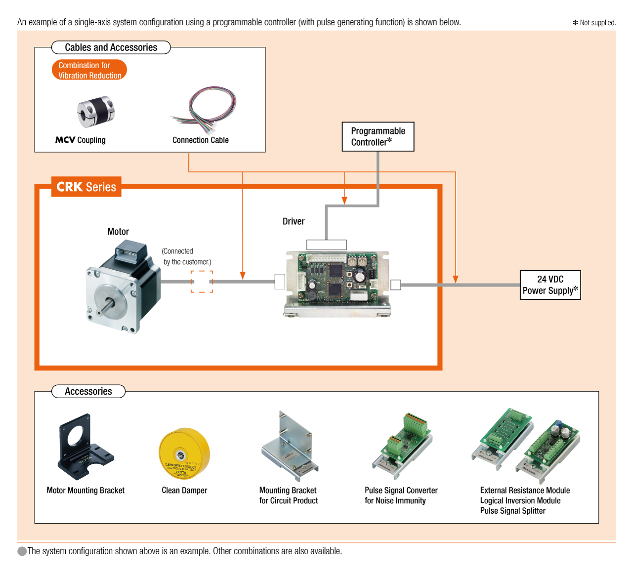
Cấu hình hệ thống