Stepper Motors PKP Series/PK Series (2-Phase)
PKP242D23A2-H50
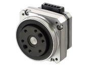
Motor


| Phân loại sản phẩm | Tên sản phẩm | Giá niêm yết | Giá niêm yết | Ngày vận chuyển |
|---|---|---|---|---|
| Motor | PKP242D23A2-H50 | SGD 908 | USD 726 | 16 Working Days |
Bao gồm
- Motor: Operating Manual
Thông số kỹ thuật
Đặc trưng
Characteristics Diagram
Kích thước
Motor
Tải dữ liệu
Các thông số kỹ thuật khác
General Specifications
| Item | Specification | |
|---|---|---|
| Operating Environment (when operating) |
Ambient Temperature | -10~+50 °C (Non-freezing) Flat Harmonic Gearhead Type is 0~+40 °C (Non-freezing) |
| Ambient Humidity | 85 % max. (Non-condensing) | |
| Atmosphere | No corrosive gases or dust No exposure to water, oil or other liquids. | |
| Temperature Rise | Winding temperature rise 80 °C max. (Based on Oriental Motor's internal measurement conditions) | |
| Stop position accuracy*1 | ±3 arc minute (±0.05˚) [PKP21□, PKP242, PKP262is ±5 arcmin (±0.083°), PK26□J, PK26□JDis ±2 arcmin (±0.034°)] |
|
| Shaft Runout | 0.05 T.I.R. (mm) *4 *5 | |
| Radial Play*2 | 0.025 mm Max. (Load 5 N) [PKP203 Load 2.5 N] |
|
| Axial Play*3 | 0.075 mm Max (Load 10 N) [PKP203・PKP21□ Load 1 N, PKP22□, PKP242, PKP262 Load 2.5 N] |
|
| Concentricity of Installation Pilot to the Shaft | 0.075 T.I.R. (mm)*4 | |
| Perpendicularity of mounting surface to the shaft | 0.075 T.I.R. (mm)*4 | |
- *1
- This is the value at full step and no load (Varies depending on the size of the load).
- *2
- Radial Play: Displacement in shaft position in the radial direction when a 5 N load (PKP203 Load 2.5 N) is applied perpendicular to the tip of the motor shaft.
- *3
- Axial Play: Displacement in shaft position in the axial direction when a 10 N load (PKP203, PKP21□ Load 1 N, PKP22□, PKP242, PKP262 Load 2.5 N) is applied to the motor shaft in the axial direction.
- *4
- T.I.R. (Total Indicator Reading): The total dial gauge reading when the measurement section is rotated 1 revolution centered on the reference axis center.
- *5
- PKP244P has 0.025 T.I.R. (mm)
Rotation Direction
This indicates the rotation direction when viewed from the output shaft side.
The rotation direction of the gearhead output shaft relative to the standard type motor output shaft varies depending on the gear type and gear ratio. Please check the following table.
| Type | Gear Ratio | Rotation Direction as Viewed From the Motor Output Shaft Side |
|---|---|---|
| TS Geared Type | 3.6, 7.2, 10 | Same direction |
| 20, 30 | Opposite direction | |
| TH Geared Type Frame size 28 mm |
7.2, 10 | Opposite direction |
| 20, 30 | Same direction | |
| TH Geared Type Frame size 42 mm, 60 mm, 90 mm |
3.6, 7.2, 10 | Same direction |
| 20, 30 | Opposite direction | |
| SH Geared Type Frame size 28 mm |
7.2, 36 | Same direction |
| 9, 10, 18 | Opposite direction | |
| SH Geared Type Frame size 42 mm, 60 mm |
3.6, 7.2, 9, 10 | Same direction |
| 18, 36 | Opposite direction | |
| SH Geared Type Frame size 90 mm |
3.6, 7.2, 9, 10, 18 | Same direction |
| 36 | Opposite direction | |
| CS Geared Type | 5, 10, 15, 20 | Same direction |
|
FC Geared Type PS Geared Type PN Geared Type HPG Geared Type |
Overall gear ratio | Same direction |
| Harmonic Geared Type | 50, 100 | Opposite direction |
Permissible Moment Load and Permissible Axial Load
When an eccentric (uneven) load is applied to the output flange-mounting surface, the load moment acts on the bearing.
Use the following formula to check whether the axial load and moment load are within specification values.
| Type | Gear Ratio | Permissible Axial Load (N) | Permissible Moment Load (N·m) | Constant a (m) |
|---|---|---|---|---|
| PKP242 | 50, 100 | 200 | 8.5 | 0.0129 |
| PKP262 | 450 | 5.0 | 0.0095 | |
| PKP262-H□S | 450 | 10.1 | 0.0140 |
The permissible moment load and permissible axial load can be calculated by the following formulas.
-
Example 1:When an external force F (N) is applied to a position that extends L (m) horizontally from the center of the output flange
-
Example 2:When an external force F (N) is applied to a position that extends L (m) vertically from the output flange-mounting surface
Inner Wiring Diagram of Motor
Bipolar (4 lead wires)
Tiêu chuẩn
Hazardous Substances
The product does not contain any substances (10 substances) exceeding the regulation values of the RoHS Directive (2011/65/EU, 2015/863/EU).
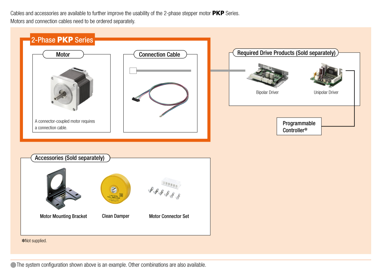
Cấu hình hệ thống