Stepper Motors RKII Series
RKS5913AAD-1
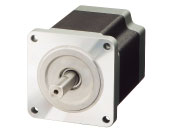
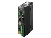
Motor/Control Circuit
| Phân loại sản phẩm | Tên sản phẩm | Giá niêm yết | Giá niêm yết | Ngày vận chuyển |
|---|---|---|---|---|
| Motor / Control Circuit | RKS5913AAD-1 | SGD 880 | USD 704 | Sản phẩm dự kiến ngừng sản xuất (30.1.2026 Đơn hàng cuối cùng) |
- *Vui lòng liên hệ với chúng tôi về việc mua sản phẩm.
- *Sản phẩm sẽ ngừng sản xuất vào ngày 31.3.2026. Vui lòng đặt hàng trước thời hạn này.
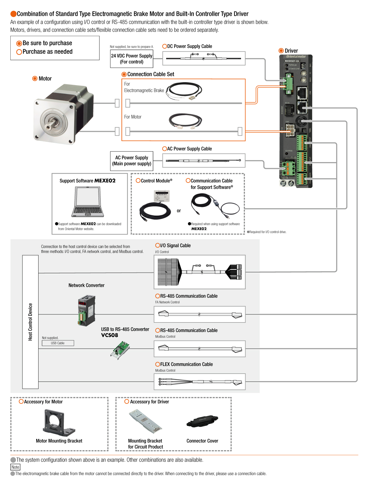
Bao gồm
- Motor, Control Circuit, Motor Connection Cable (1 m), Connector for Power Input Terminal, Connector for Main Power Input Terminal, Sensor Signal Connector, Input Signal Connector, Output Signal Connector
Thông số kỹ thuật
Tải dữ liệu
Các thông số kỹ thuật khác
Driver Specifications
| Built-in Controller Type | Pulse input type | |
|---|---|---|
| Maximum Input Pulse Frequency | − |
Line driver output by host controller: 500 kHz (at 50 % duty) Open-Collector Output by Host Controller: 250 kHz (at 50 % duty) Negative logic pulse input |
| Input Signals | Photocoupler Input, Input Signal Voltage: 11.4 V~26.4 V |
Photocoupler Input, Input Signal Voltage: 11.4 V~26.4 V (AWO, CS, FREE, ALM-RST) Photocoupler Input, Input Signal Voltage: 3 V~5.25 V (CW (PLS) +5 V, CCW (DIR) +5 V) Photocoupler Input, Input Signal Voltage: 21.6 V~26.4 V (CW (PLS) +24 V, CCW (DIR) +24 V) |
| Output Signals |
Photocoupler and Open-Collector Output External operating conditions: 30VDC 10 mA max. |
Photocoupler and Open-Collector Output External operating conditions: 30VDC 10 mA max. (READY, ALM, TIM) |
| Number of Positioning Data Sets | 64 Points | − |
| Positioning Operation | Independent, linked, linked 2, sequential, direct | − |
| Other operations | Continuous operation, JOG operation, return-to-home operation, Test Operation |
− |
| Control Module OPX-2A |
O | − |
| Support Software MEXE02 |
O | − |
General Specifications
| Motor | Driver | |||
|---|---|---|---|---|
| Built-in Controller Type | Pulse input type | |||
| Thermal Class | 130 (B) [UL is 105 (A) certified] |
− | ||
| Insulation Resistance |
100 MΩ or more when a 500 VDC megger is applied between the following places.
|
100 MΩ or more when a 500 VDC megger is applied between the following places.
|
||
| Dielectric Strength |
Sufficient to withstand the following for 1 minute:
|
Sufficient to withstand the following for 1 minute: | ||
|
|
|||
| Operating Environment (when operating) |
Ambient Temperature |
-10~+50 °C (Non-freezing): Standard Type TS/PS/FC geared type 0~+50 °C (Non-freezing): With encoder 0~+40 °C (Non-freezing): Harmonic Geared Type According to Oriental Motor’s measurement conditions |
0~+55 °C*2 (Non-freezing) | |
| Ambient Humidity | 85 % max. (Non-condensing) | |||
| Atmosphere | No corrosive gases or dust. No exposure to water, oil or other liquids. | |||
| Temperature Rise | 5-phase excitation at rated current, 80 °C max. at standstill Temperature rise of winding section at 80 °C or less (resistance change method) |
− | ||
| Degree of Protection | IP20 | IP10 | IP20 | |
| Stop position accuracy*3 | ±3 arc minute (±0.05˚) | |||
| Shaft Runout | 0.05 T.I.R. (mm)*4 | − | ||
| Radial Play*5 | 0.025 mm Max. (Load 5 N) | − | ||
| Axial Play*6 | 0.075 mm Max. (Load 10 N) | − | ||
| Concentricity of Installation Pilot to the Shaft |
0.075 T.I.R. (mm)*4 | − | ||
| Perpendicularity of mounting surface to the shaft |
0.075 T.I.R. (mm)*4 | − | ||
- *1
- (Only for types with electromagnetic brake)
- *2
- When a heat sink of a capacity at least equivalent to an aluminum plate with a size of 200×200 mm and 2 mm thickness
- *3
- 0.72˚ is the value under no load. (The value changes with the size of the load.)
- *4
- T.I.R. (Total Indicator Reading): The total dial gauge reading when the measurement section is rotated 1 revolution centered on the reference axis center.
- *5
- Radial Play: Displacement in shaft position in the radial direction when a 5 N load is applied perpendicular to the tip of the motor shaft.
- *6
- Axial Play: Displacement in shaft position in the axial direction when a 10 N load is applied to the motor shaft in the axial direction.
Note
- Disconnect the motor and driver when measuring insulation resistance, or conducting a dielectric strength test.
Permissible Radial Load and Permissible Axial Load
Unit: N
| Type | Motor Frame Size |
Type | Gear Ratio | Permissible Radial Load | Permissible Axial Load | ||||
|---|---|---|---|---|---|---|---|---|---|
| Distance From Shaft End [mm] | |||||||||
| 0 | 5 | 10 | 15 | 20 | |||||
| Standard Type | 42 mm | PKE54 | − | 35 | 44 | 58 | 85 | − | 15 |
| 60 mm | PKE56 | 90 | 100 | 130 | 180 | 270 | 30 | ||
| 85 mm | PKE59 | 260 | 290 | 340 | 390 | 480 | 60 | ||
| TS Geared Type | 42 mm | PKE54 | 3.6, 7.2, 10 | 20 | 30 | 40 | 50 | − | 15 |
| 20, 30 | 40 | 50 | 60 | 70 | − | ||||
| 60 mm | PKE56 | 3.6, 7.2, 10 | 120 | 135 | 150 | 165 | 180 | 40 | |
| 20, 30 | 170 | 185 | 200 | 215 | 230 | ||||
| 90 mm | PKE59 | 3.6, 7.2, 10 | 300 | 325 | 350 | 375 | 400 | 150 | |
| 20, 30 | 400 | 450 | 500 | 550 | 600 | ||||
| PS Geared Type | 42 mm | PKE54 | 5 | 70 | 80 | 95 | 120 | - | 100 |
| 7.2 | 80 | 90 | 110 | 140 | - | ||||
| 10 | 85 | 100 | 120 | 150 | - | ||||
| 25 | 120 | 140 | 170 | 210 | - | ||||
| 36 | 130 | 160 | 190 | 240 | - | ||||
| 50 | 150 | 170 | 210 | 260 | - | ||||
| 60 mm | PKE56 | 5 | 170 | 200 | 230 | 270 | 320 | 200 | |
| 7.2 | 200 | 220 | 260 | 310 | 370 | ||||
| 10 | 220 | 250 | 290 | 350 | 410 | ||||
| 25 | 300 | 340 | 400 | 470 | 560 | ||||
| 36 | 340 | 380 | 450 | 530 | 630 | ||||
| 50 | 380 | 430 | 500 | 600 | 700 | ||||
| 90 mm | PKE59 | 5 | 380 | 420 | 470 | 540 | 630 | 600 | |
| 7.2 | 430 | 470 | 530 | 610 | 710 | ||||
| 10 | 480 | 530 | 590 | 680 | 790 | ||||
| 25 | 650 | 720 | 810 | 920 | 1070 | ||||
| 36 | 730 | 810 | 910 | 1040 | 1210 | ||||
| 50 | 820 | 910 | 1020 | 1160 | 1350 | ||||
| Harmonic Geared Type | 42 mm | PKE54 | 50, 100 | 180 | 220 | 270 | 360 | 510 | 220 |
| 60 mm | PKE56 | 320 | 370 | 440 | 550 | 720 | 450 | ||
| 90 mm | PKE59 | 1090 | 1150 | 1230 | 1310 | 1410 | 1300 | ||
| FC Geared Type | 42 mm | PKE54 | 7.2, 10, 20, 30 | 180 | 200 | 220 | 250 | - | 100 |
| 60 mm | PKE56 | 270 | 290 | 310 | 330 | 350 | 200 | ||
- The product names are listed such that the product names are distinguishable.
-
The PS Geared Type has a lifetime of 20,000 hours, when either the permissible radial load or the permissible axial load is applied.
Click here for information about gearhead life
Radial Load and Axial Load
Rotation Direction
This indicates the rotation direction when viewed from the output shaft side.
The rotation direction of the gearhead output shaft relative to the standard type motor output shaft varies depending on the gear type and gear ratio. Please check the following table.
| Type | Gear Ratio | Rotation Direction as Viewed From the Motor Output Shaft Side |
|---|---|---|
| TS Geared Type | 3.6, 7.2, 10 | Same direction |
| 20, 30 | Opposite direction | |
| TH Geared Type Frame size 28 mm |
7.2, 10 | Opposite direction |
| 20, 30 | Same direction | |
| TH Geared Type Frame size 42 mm, 60 mm, 90 mm |
3.6, 7.2, 10 | Same direction |
| 20, 30 | Opposite direction | |
| SH Geared Type Frame size 28 mm |
7.2, 36 | Same direction |
| 9, 10, 18 | Opposite direction | |
| SH Geared Type Frame size 42 mm, 60 mm |
3.6, 7.2, 9, 10 | Same direction |
| 18, 36 | Opposite direction | |
| SH Geared Type Frame size 90 mm |
3.6, 7.2, 9, 10, 18 | Same direction |
| 36 | Opposite direction | |
| CS Geared Type | 5, 10, 15, 20 | Same direction |
|
FC Geared Type PS Geared Type PN Geared Type HPG Geared Type |
Overall gear ratio | Same direction |
| Harmonic Geared Type | 50, 100 | Opposite direction |
RS-485 Communication Specifications
| Protocol | Modbus RTU Mode |
|---|---|
| Electrical Characteristics | EIA-485 Compliant, Straight Cable Use twisted-pair cables (TIA/EIA-568B CAT5e or better recommended). The max. total extension length is 50 m.* |
| Mode | Half duplex and asynchronous mode (data: 8 bits, stop bit: 1 bit or 2 bits, parity: none, even, or odd) |
| Transmission Rate | 9600bps/19200bps/38400bps/57600bps/115200bps |
| Connection Type | A maximum of 31 units can be connected to a single host connection device. |
- *If a specific wiring and layout causes the motor cable or power supply cable to generate a noise problem, shield the cable or use ferrite cores.
Encoder Specifications
| Resolution | 500P/R |
|---|---|
| Output Mode | Incremental |
| Output Signals | 3 channels |
| Output Circuit Type | Line Driver |
Tiêu chuẩn
Regulations and Standards Materials
Documents about compliance with regulations and standards can be downloaded from the "Data Download" tab on the product details page.
(The types of files available for download vary by product.)
Explanations of the Global Laws, Regulations and Standards can be found here.
Information about our compliance with regulations and standards for each of our product series can be found here.
Hazardous Substances
The product does not contain any substances (10 substances) exceeding the regulation values of the RoHS Directive (2011/65/EU, 2015/863/EU).
Cấu hình hệ thống
Những sản phẩm tương tự
Network Converter
| Products | Features | ||
|---|---|---|---|
NETC02-CC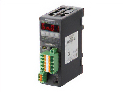
|
Features |
[CC-Link Ver. 2 Compatible] By supporting CC-Link Ver.2, you can simplify the ladder program and shorten the communication time for data sending and receiving. |
|
| Products |
NETC01-CC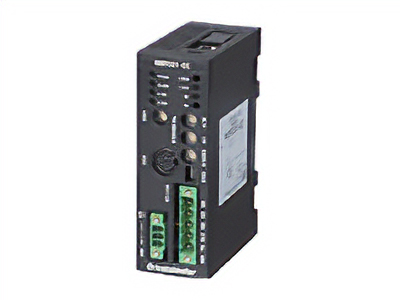
|
Features |
[CC-Link Ver.1.1 Compatible] By connecting a network converter, you can complete the wiring process with a single dedicated cable approved for the CC-Link communication protocol. |
| Products |
NETC01-M2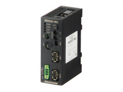
|
Features |
[MECHATROLINK-II Compatible] By connecting a network converter, the wiring process can be completed with a single dedicated cable approved for the MECHATROLINK-II communication protocol. |
| Products |
NETC01-M3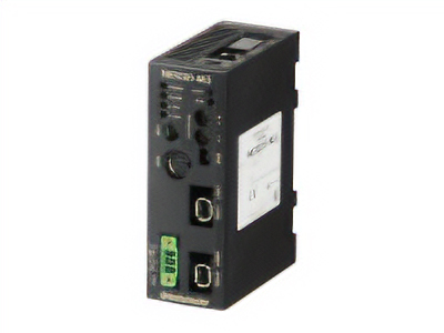
|
Features |
[MECHATROLINK-III Compatible] By connecting a network converter, the wiring process can be completed with a single dedicated cable approved for the MECHATROLINK-III communication protocol. |
| Products |
NETC01-ECT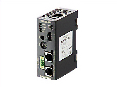
|
Features |
[EtherCAT Compatible] |