Stepper Motors RKII Series
RKSD507-C
Control Circuit
| Phân loại sản phẩm | Tên sản phẩm | Giá niêm yết | Giá niêm yết | Ngày vận chuyển |
|---|---|---|---|---|
| Control Circuit | RKSD507-C | SGD 495 | USD 396 | 11 Working Days |
• Specifications and various data of combination products may be shown on the combination product page. Please check the page of the combination product.
Bao gồm
- Control Circuit: Connector for Main Power Input Terminal, Connector for Pulse Input, I/O Signal Connector
Thông số kỹ thuật
Kích thước
Control Circuit
Tải dữ liệu
Các thông số kỹ thuật khác
Driver Specifications
| Built-in Controller Type | Pulse input type | |
|---|---|---|
| Maximum Input Pulse Frequency | − |
Line driver output by host controller: 500 kHz (at 50 % duty) Open-Collector Output by Host Controller: 250 kHz (at 50 % duty) Negative logic pulse input |
| Input Signals | Photocoupler Input, Input Signal Voltage: 11.4 V~26.4 V |
Photocoupler Input, Input Signal Voltage: 11.4 V~26.4 V (AWO, CS, FREE, ALM-RST) Photocoupler Input, Input Signal Voltage: 3 V~5.25 V (CW (PLS) +5 V, CCW (DIR) +5 V) Photocoupler Input, Input Signal Voltage: 21.6 V~26.4 V (CW (PLS) +24 V, CCW (DIR) +24 V) |
| Output Signals |
Photocoupler and Open-Collector Output External operating conditions: 30VDC 10 mA max. |
Photocoupler and Open-Collector Output External operating conditions: 30VDC 10 mA max. (READY, ALM, TIM) |
| Number of Positioning Data Sets | 64 Points | − |
| Positioning Operation | Independent, linked, linked 2, sequential, direct | − |
| Other operations | Continuous operation, JOG operation, return-to-home operation, Test Operation |
− |
| Control Module OPX-2A |
O | − |
| Support Software MEXE02 |
O | − |
General Specifications
| Motor | Driver | |||
|---|---|---|---|---|
| Built-in Controller Type | Pulse input type | |||
| Thermal Class | 130 (B) [UL/CSA certified at 105 (A)] |
− | ||
| Insulation Resistance |
100 MΩ or more when a 500 VDC megger is applied between the following places.
|
100 MΩ or more when a 500 VDC megger is applied between the following places.
|
||
| Dielectric Strength |
Sufficient to withstand the following for 1 minute.
|
Sufficient to withstand the following for 1 minute. |
||
|
|
|||
| Operating Environment (when operating) |
Ambient Temperature | -10~+50 °C (Non-freezing) | 0~+55 °C* (Non-freezing) | |
| Ambient Humidity | 85 % max. (Non-condensing) | |||
| Atmosphere | No corrosive gases or dust. No exposure to water, oil or other liquids. |
|||
| Temperature Rise | 5-phase excitation at rated current, 80 °C max. at standstill Temperature rise of winding section at 80 °C or less (resistance change method) |
− | ||
| Degree of Protection | IP20 | IP10 | IP20 | |
- *When installing a heat sink equivalent to an aluminum plate min. 200×200 mm, thickness 2 mm
Note
- Do not measure insulation resistance or perform a dielectric strength test while the motor and driver are connected.
General Specifications
| Motor | Driver | |||
|---|---|---|---|---|
| Built-in Controller Type | Pulse input type | |||
| Thermal Class | 130 (B) [UL is 105 (A) certified] |
− | ||
| Insulation Resistance |
100 MΩ or more when a 500 VDC megger is applied between the following places.
|
100 MΩ or more when a 500 VDC megger is applied between the following places.
|
||
| Dielectric Strength |
Sufficient to withstand the following for 1 minute:
|
Sufficient to withstand the following for 1 minute: | ||
|
|
|||
| Operating Environment (when operating) |
Ambient Temperature |
-10~+50 °C (Non-freezing): Standard Type TS/PS/FC geared type 0~+50 °C (Non-freezing): With encoder 0~+40 °C (Non-freezing): Harmonic Geared Type According to Oriental Motor’s measurement conditions |
0~+55 °C*2 (Non-freezing) | |
| Ambient Humidity | 85 % max. (Non-condensing) | |||
| Atmosphere | No corrosive gases or dust. No exposure to water, oil or other liquids. | |||
| Temperature Rise | 5-phase excitation at rated current, 80 °C max. at standstill Temperature rise of winding section at 80 °C or less (resistance change method) |
− | ||
| Degree of Protection | IP20 | IP10 | IP20 | |
| Stop position accuracy*3 | ±3 arc minute (±0.05˚) | |||
| Shaft Runout | 0.05 T.I.R. (mm)*4 | − | ||
| Radial Play*5 | 0.025 mm Max. (Load 5 N) | − | ||
| Axial Play*6 | 0.075 mm Max. (Load 10 N) | − | ||
| Concentricity of Installation Pilot to the Shaft |
0.075 T.I.R. (mm)*4 | − | ||
| Perpendicularity of mounting surface to the shaft |
0.075 T.I.R. (mm)*4 | − | ||
- *1
- (Only for types with electromagnetic brake)
- *2
- When a heat sink of a capacity at least equivalent to an aluminum plate with a size of 200×200 mm and 2 mm thickness
- *3
- 0.72˚ is the value under no load. (The value changes with the size of the load.)
- *4
- T.I.R. (Total Indicator Reading): The total dial gauge reading when the measurement section is rotated 1 revolution centered on the reference axis center.
- *5
- Radial Play: Displacement in shaft position in the radial direction when a 5 N load is applied perpendicular to the tip of the motor shaft.
- *6
- Axial Play: Displacement in shaft position in the axial direction when a 10 N load is applied to the motor shaft in the axial direction.
Note
- Disconnect the motor and driver when measuring insulation resistance, or conducting a dielectric strength test.
Tiêu chuẩn
Regulations and Standards Materials
Documents about compliance with regulations and standards can be downloaded from the "Data Download" tab on the product details page.
(The types of files available for download vary by product.)
Explanations of the Global Laws, Regulations and Standards can be found here.
Information about our compliance with regulations and standards for each of our product series can be found here.
Hazardous Substances
The product does not contain any substances (10 substances) exceeding the regulation values of the RoHS Directive (2011/65/EU, 2015/863/EU).
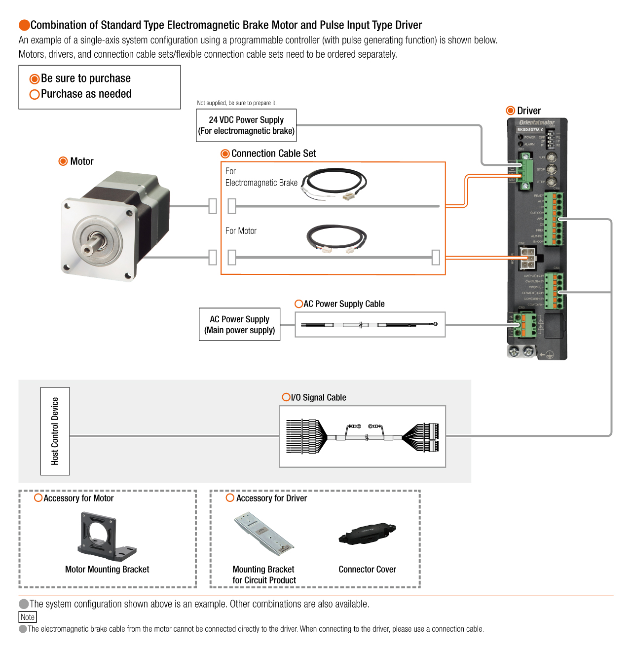
Cấu hình hệ thống